background image

DRAINAGE

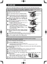
Prepare for drainage and drain out water within the unit in the following cases.

If the unit stops operating and the TIMER, OPERATION and MEGA COOL lamps are 
blinking.  (This indicates that the water tank inside the unit is full.)

1

  Make sure to turn the unit off.

2

  Turn the drainage nozzle to the OPEN position.

3

  Pull the stopcock out from the drainage nozzle.

•  When the stopcock is removed, a small amount of 

water may be discharged from the drainage nozzle.

4

 Attach the drain grommet to a standard com-

mercially available hose. (5/8" inner diameter, 
7/8" outer diameter)

5

  Attach the hose to the drainage nozzle, and se-

cure it with the hose band.

•  Prepare for draining, as drain water will come out 

through the hose during operation.

6

  Press the POWER button on the unit twice.

• The water will drain out through the drainage 

hose. Maximum amount of water that may be 
drained out is approximately 4

1/5

 pints.

• The OPERATION, TIMER and MEGA COOL 

lamps will be blinking.

7

 When drainage water stops running out from 

the hose, turn the unit off by pressing POWER 
button.

•  This will take about one minute.

8

 Remove the hose from the drainage nozzle, and replace the stopcock.

•  Keep the hose band and drain grommet in case of re-used.

9

 Turn the drainage nozzle to the CLOSE position.

Whenever the unit is moved (to prevent water within the unit from spilling).
When the unit is not used for a long time.

1

  Carry out the above procedures from 1 to 5.

2

  Press the POWER button on the unit.

•  The water will drain out through the drainage hose.
  Maximum amount of water that may be drained out is approximately 4

1/5

 pints.

•  The OPERATION lamps will light.

3

  When drainage water stops running out from the hose, turn the unit off by pressing 

POWER button.

•  This will take about one minute.

4

 Remove the hose from the drainage nozzle, and replace the stopcock.

•  Keep the hose band and drain grommet in case of re-used.

5

 Turn the drainage nozzle to the CLOSE position.

6

 Remove the stopcock from the drainpipe nozzle, and completely drain any water 

within the unit.

• Always prepare a receptacle to collect the water 

before draining. Maximum amount of water that 
may be drained out is approximately 

2/5

 pints.

7

 Replace the stopcock to the drainpipe nozzle.

E-26

Stopcock

Drainpipe nozzle

Drainage nozzle

Stopcock

Drain grommet

Hose

"OPEN" position

Hose band

Summary of Contents for CV-13NH

Page 1: ...PORTABLE TYPE ROOM AIR CONDITIONER INSTALLATION AND OPERATION MANUAL ACONDICIONADOR DE AIRE PARA HABITACIÓN TIPO PORTÁTIL MANUAL DE INSTALACIÓN Y FUNCIONAMIENTO ENGLISH CV 13NH ESPAÑOL ...

Page 2: ......

Page 3: ...R LIMITED WARRANTY E 3 PRECAUTIONS E 4 LOCATION E 7 INCLUDED E 7 PART NAMES E 8 INSTALL WINDOW PANEL E 10 INSTALLATION AND REMOVAL OF EXHAUST HOSE E 14 PRE OPERATION CHECKS E 16 COOL MODE E 18 DEHUMIDIFICATION MODE E 19 FAN MODE E 20 VENTILATION MODE E 20 TO CHANGE AIR FLOW DIRECTION E 21 MEGA COOL OPERATION E 22 SLEEP OPERATION E 22 TIMER OPERATION E 23 MAIN UNIT OPERATION E 25 DRAINAGE E 26 MAIN...

Page 4: ...p Authorized Servicer PARTS for your Authorized Parts Distributor ACCESSORIES ADDITIONAL CUSTOMER INFORMATION TO WRITE For service problems warranty information missing items and other assistance Sharp Electronics Corporation Customer Assistance Center 1300 Naperville Drive Romeoville IL 60446 1091 TO ACCESS THE INTERNET www sharpusa com Please provide the following information when you write or c...

Page 5: ...described herein shall constitute complete fulfillment of all liabilities and responsibilities of Sharp to the purchaser with respect to the Product and shall constitute full satisfaction of all claims whether based on contract negligence strict liability or otherwise In no event shall Sharp be liable or in any way responsible for any damages or defects in the Product which were caused by repairs ...

Page 6: ...er supply WARNING FOR POWER SUPPLY CORD This air conditioner uses a plug with a built in fuse Read the precautions on the plug before using the air conditioner Always conduct a Power Plug Check See Page 16 before use to confirm the power plug functions normally This power plug must only be plugged into an appropriate wall socket Do not use in conjunction with any extension cords Push the power plu...

Page 7: ...ature around the drainage hose must not be below freezing point when used Drained water may freeze inside the hose causing water inside the unit to overflow into the room Do not block the exhaust air outlet with obstacles Cooling performance may be reduced or stop completely Grounded electrical box Improper use of the grounding plug can result in the risk of electric shock This appliance must be g...

Page 8: ... the unit This air conditioner blows the warm air generated by the unit outside the room via the exhaust hose while in cool mode Accordingly the same amount of air as that blown out will enter the room from outside through any openings into the room When cooling operation is performed at high humidity conditions water tank in side the unit may frequently become full When water tank inside the unit...

Page 9: ...o not attempt to roll the unit over objects The unit must be placed within reach of a properly rated grounded socket Never place any obstacles around the air inlet or outlet of the unit Allow at least 12 30cm of space from the wall for ef ficient air conditioning MIN 12 30cm MIN 12 30cm INCLUDED E 7 SUGGESTED TOOLS FOR WINDOW PANEL INSTALLATION 1 Screwdriver medium size Phillips 2 Tape measure or ...

Page 10: ...green 9 Air inlet REAR VIEW NOTE Actual unit might vary slightly from above illustration FRONT VIEW 0 Exhaust air outlet q Window exhaust adapter w Exhaust hose e Remote control hook r Air filters t Drainage nozzle and stopcock y Power supply cord hooks u Drainpipe nozzle and stopcock i Power supply cord o Power plug p Casters 4 E 8 1 2 3 4 5 6 7 8 9 9 9 0 q w e r t y u i o p ...

Page 11: ... SYMBOL y SLEEP SYMBOL u FAN SPEED SYMBOLS AUTO Manual setting i TEMPERATURE AND TIMER COUNT DOWN INDICATOR o TRANSMITTING SYMBOL p ON TIMER OFF TIMER SYMBOL REMOTE CONTROL DISPLAY 1 2 3 4 5 6 7 8 9 0 q w e r t y u i o p Quiet Low High Light absorbing material is used for the POWER button Keep the remote control in a lighted place for several hours in order for the button to absorb light The butto...

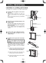
Page 12: ...ure that its four projections fit into the holes in the window panel Side A will now be at the top as indicated in the diagram 3 Cut the foam seal A adhesive type to the proper length and attach it to the window stool 4 Attach the window panel to the window stool If the inner width of the window is be tween 22 559mm and 24 609mm inclusive The window panel cannot be installed in windows less than 2...

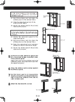
Page 13: ...ace the window panel on the window stool 3 Slide the adjustment and extension panels to fit the window frame width 4 Secure the window panel to the window stool with 4 screws 5 Cut the foam seals adhesive type A and B to the proper length and attach it to the window panel Attach foam seal A to the window panel and extension panel and attach foam seal B to the adjustment panel 6 Close the window sa...

Page 14: ... holes in the window panel Side A will now be at the top as indicated in the diagram when it is installed in the window 3 Cut the foam seal A adhesive type to the proper length and attach it to the window frame 4 Install the window panel into the window frame If the inner height of the window is between 22 559mm and 24 609mm inclusive The window panel cannot be installed in windows less than 22 55...

Page 15: ...ide the adjustment and extension panels to fit the window frame height 4 Secure the window panel to the window frame with 4 screws 5 Cut the foam seals adhesive type A and B to the proper length and attach them to the window panel Attach foam seal A to the window panel and extension panel and attach foam seal B to the adjustment panel 6 Close the window sash securely against the Window panel 7 Cut...

Page 16: ...re they are securely attached 2 Attach the exhaust hose adapter to the unit Insert the two projections on the ex haust hose adapter into the two holes on the unit and firmly attach them to each other 3 Slide and open the exhaust cover on the window panel and attach the win dow exhaust adapter Surface of window exhaust adapter marked TOP should be at the top when it is installed in a double hung sa...

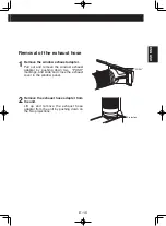
Page 17: ...apter Pull out and remove the window exhaust adapter by pushing down two PUSH markings and slide and close the exhaust cover in the window panel 2 Remove the exhaust hose adapter from the unit Lift up and remove the exhaust hose adapter from the unit by pushing down on the two projections ...

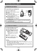
Page 18: ...r plug before use 1 Press the RESET button 2 Insert the power plug into the wall socket 3 Press the TEST button You will hear a CLICK if the circuit breaker is functioning correctly 4 Press the RESET button until you hear another CLICK The circuit breaker is activated power is supplied and the air conditioner is now ready for use Do not attempt to use the air conditioner if the above procedure can...

Page 19: ...sed to direct sunlight or near a heater Pro tect the remote control from moisture and shock which can discolor or damage it Point the remote control towards the units signal receiver window and press the desired button A beep will sound when the unit re ceives the signal Make sure nothing such as curtains blocks the signal receiver window The remote control operates up to 23 feet 7 meters away HOW...

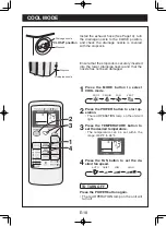
Page 20: ... nozzle Stopcock CLOSE position Stopcock Drainpipe nozzle 1Press the MODE button to select COOL mode COOL DEHUM FAN VENT 2Press the POWER button to start op eration The red OPERATION lamp on the unit will light 3Press the TEMPERATURE button to set the desired temperature The temperature can be set within the range of 64 F to 86 F 4Press the FAN button to set the de sired fan speed AUTO QUIET LOW H...

Page 21: ...Always perform this procedure with the unit turned off Drain water will spout out if attempted during operation 4 Attach the drain grommet to a standard commer cially available hose 5 8 inner diameter 7 8 outer diameter 5 Attach the hose to the drainage nozzle and se cure it with the hose band Insert the hose securely into a container with a minimum capacity of 31 2 gallons Be sure to monitor the ...

Page 22: ...r drainpipe nozzle and that the nozzle has not been damaged 1 Press the MODE button to select FAN mode COOL DEHUM FAN VENT 2 Press the POWER button to start operation The red OPERATION lamp on the unit will light The temperature cannot be set 3 Press the FAN button to set the desired fan speed QUIET LOW HIGH TO TURN OFF Press the POWER button again The red OPERATION lamp on the unit will turn off ...

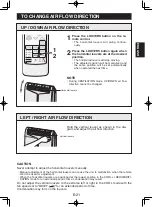
Page 23: ...rized and the same position will be set automatically when operated the next time LEFT RIGHT AIR FLOW DIRECTION CAUTION Never attempt to adjust the horizontal louvers manually Manual adjustment of the horizontal louvers can cause the unit to malfunction when the remote control is used for adjustment When the horizontal louvers are positioned at the lowest position in the COOL or DEHUMIDIFI CATION ...

Page 24: ...or 30 minutes in MEGA COOL mode The extra high fan speed may automatically slow down to protect the unit SLEEP operation and MEGA COOL operation can not be used together 1 Press the SLEEP button during cooling mode The remote control displays The orange TIMER lamp on the unit will light The unit will stop operating after 8 hours The fan speed setting is set to AUTO TO CANCEL Press the SLEEP button...

Page 25: ... setting will change as you press the but ton as follows Hold the button down to speed through the set tings The orange TIMER lamp on the unit will light The unit will emit a beep when it receives the sig nal The time setting will count down to show the re maining time TO CANCEL TIMER Press the CANCEL button The orange TIMER lamp on the unit will turn off Select the mode temperature and fan speed ...

Page 26: ... set from a minimum of half an hour 30 minutes to a maxi mum of 12 hours Up to 9 5 hours you can set in half hour 30 minutes increments and from 10 to 12 hours in 1 hour increments OFF TIMER 1 Point the remote control at the signal receiver win dow on the unit 1Press the OFF TIMER button and set the time as desired The time setting will change as you press the but ton as follows Hold the button do...

Page 27: ...operated it will resume operation at its last settings If the unit has been unplugged since it was last operated it will resume operation in the cooling mode set at 68 F The fan speed set to AUTO TO TURN OFF Press the POWER button again The red OPERATION lamp on the unit will turn off NOTES Upon starting MAIN UNIT operation the drainage pump inside the unit runs for about a minute which may produc...

Page 28: ...button This will take about one minute 8Remove the hose from the drainage nozzle and replace the stopcock Keep the hose band and drain grommet in case of re used 9Turn the drainage nozzle to the CLOSE position Whenever the unit is moved to prevent water within the unit from spilling When the unit is not used for a long time 1 Carry out the above procedures from 1 to 5 2 Press the POWER button on t...

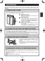
Page 29: ...ely if the insect guard net becomes clogged with dust Periodically remove the window exhaust adapter from the window panel and clean the insect guard net with a vacuum cleaner Filters E 27 Be sure to disconnect the power from the wall socket before performing any main tenance CLEANING THE FILTERS If the filter is clogged with dust the airflow will be reduced resulting in poor cooling perform ance ...

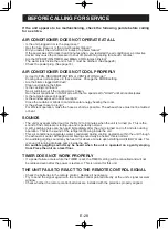
Page 30: ...e too long For efficient operation make the hose as short as possible The exhaust hose must not be twisted or bent SOUNDS The unit may seem rather loud for the first 2 to 3 minutes when the unit is turned on This is the sound of the compressor starting up and is perfectly normal A soft swishing noise can be heard immediately after the unit is turned on or off and also during operation This is the ...

Page 31: ...CLUIDAS S 7 DESIGNACIÓN DE LAS PIEZAS S 8 INSTALACIÓN DEL PANEL DE VENTANA S 10 INSTALACIÓN Y DESMONTAJE DE LA MANGUERA DE ESCAPE S 14 REVISIONES ANTES DE INICIAR EL FUNCIONAMIENTO S 16 MODO ENFRIAR S 18 MODO DESHUMIDIFICACIÓN S 19 MODO VENTILADOR S 20 MODO VENTILACIÓN S 20 CAMBIO DE LA DIRECCIÓN DE LA CORRIENTE DE AIRE S 21 FUNCIONAMIENTO MEGA COOL S 22 FUNCIONAMIENTO DE DORMIR S 22 FUNCIONAMIENT...

Page 32: ...1 800 BE SHARP 237 4277 para SERVICIO para su centro de servicio autorizado Sharp más cercano PIEZAS para su distribuidor autorizado de piezas ACCESORIOS INFORMACIÓN ADICIONAL PARA LOS CLIENTES CORRESPONDENCIA Sobre problemas de servicio información de garantía ítems perdidos y otras ayudas Sharp Electronics Corporation Customer Assistance Center 1300 Naperville Drive Romeoville IL 60446 1091 ACCE...

Page 33: ...to negligencia marco legal u otros En ninguna circunstancia Sharp será responsable por cualquier daño o defectos en el Producto causados por reparaciones o intentos de reparaciones hechos por cualquier persona excepto los centros de sercicio autorizados por Sharp En ninguna circunstancia Sharp será responsable por daños incidentales o consecuentes económicos o daño de propiedades Algunos estados n...

Page 34: ...RO DE EN ERGÍA Este acondicionador de aire utiliza una clavija con un fusible incorporado Lea las precauciones sobre la clavija de conexión antes de utilizar el acondicionador de aire Antes de utilizar el producto realice siempre una Revisión de la clavija de toma de corriente vea la página 16 para confirmar que la clavija de toma de corriente funciona normalmente Esta clavija de toma de corriente...

Page 35: ...o Debe de realizarse el drenaje cada vez que mueva el acondicionador de aire Vea la página 26 Si queda algo de agua en el depósito podría derramarse al moverse Retire el panel de ventana en caso de condiciones atmósfericas adversas Condiciones atmósfericas extremas pueden ocasionar la entrada de agua a través de las apertu ras Para asegurar un drenaje adecuado la manguera de drenaje no debe de ten...

Page 36: ... hab itación a través de la manguera de escape cuando se encuentra en el modo enfriar Por consiguiente la misma cantidad de aire inyectada hacia el exterior entrará en la habitación desde el exterior a través de cualquier apertura en la habitación Cuando la función de enfriamiento se lleva a cabo en condiciones de alta humedad el depósito de agua localizado dentro de la unidad puede llenarse frecu...

Page 37: ...de aire de la unidad Deje un espacio de por lo menos 12 30 cm con respecto a la pared para un acondicionamiento de aire eficaz MÍN 12 30 cm MÍN 12 30 cm PIEZAS INCLUIDAS HERRAMIENTAS SUGERIDAS PARA LA INSTALACIÓN DEL PANEL DE VENTANA 1 Destornillador Phillips tamaño mediano 2 Cinta métrica o regla 3 Cuchillo o tijeras 4 Sierra En el caso de que el panel de ventana necesite cortarse debido a que la...

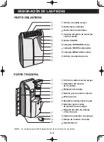
Page 38: ...ERA NOTA La unidad puede diferir ligeramente de la ilustración de arriba PARTE DELANTERA 0 Orificio de salida de aire de escape q Adaptador del escape de la ventana w Manguera de escape e Gancho para el control remoto r Filtros de aire t Boquilla de drenaje y llave de paso y Ganchos para el cable de suministro de energía u Boquilla del tubo de drenaje y llave de paso i Cable de suministro de energ...

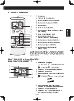
Page 39: ...VENTILADOR VENTILACIÓN t SÍMBOLO DE SUPERENFRIAMIENTO y SÍMBOLO DE SLEEP u SÍMBOLOS DE VELOCIDAD DEL VENTILADOR AUTOMÁTICO Ajuste manual i INDICADOR DE TEMPERATURA Y CUENTA ATRÁS DEL TEMPORIZADOR o SÍMBOLO DE TRANSMISIÓN p SÍMBOLO DEL TEMPORIZADOR DE ACTIVACIÓN DESACTIVACIÓN PANTALLA DE VISUALIZACIÓN DEL CONTROL REMOTO 1 2 3 4 5 6 7 8 9 0 q w e r t y u i o p BAJA ALTA SILENCIOSA Se utiliza materia...

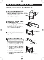
Page 40: ...ntra insectos para asegurarse de que las cuatro salientes se hayan encajado dentro de los agujeros en el panel de ventana El lado A estará ahora en la parte supe rior como se indica en el diagrama 3 Corte el sello de espuma A tipo adhesivo a la longitud adecuada y péguelo en el antepecho de ventana 4 Fije el panel de ventana al antepecho Si el ancho interior de la ventana esta en tre 22 559 mm y 2...

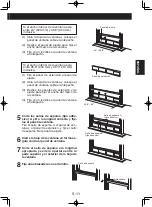
Page 41: ...ventana sobre el antepecho 3 Deslice los paneles de extensión y de ajuste para fijar el ancho del marco de la ventana 4 Fije con 4 tornillos el panel de ventana al antepecho 5 Corte los sellos de espuma tipo adhe sivo A y B a la longitud correcta y fíje los al panel de ventana Fije el sello de espuma A al panel de ven tana y al panel de extensión y fije el sello de espuma B al panel de ajuste 6 Ci...

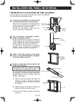
Page 42: ...as cuatro salientes se hayan encajado dentro de los agujeros en el panel de ventana El lado A estará ahora en la parte superior como se indica en el diagrama cuando este se instala en la ventana 3 Corte el sello de espuma A tipo adhe sivo a la longitud adecuada y péguelo en el marco de la ventana 4 Instale el panel de ventana dentro del marco de la ventana Si la altura interior de la ventana esta ...

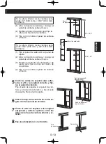
Page 43: ...extensión y de ajuste para fijar la altura del marco de la ventana 4 Fije con 4 tornillos el panel de ventana al marco 5 Corte los sellos de espuma tipo adhe sivo A y B a la longitud correcta y fíje los al panel de ventana Fije el sello de espuma A al panel de ven tana y al panel de extensión y fije el sello de espuma B al panel de ajuste 6 Cierre la hoja de la ventana en forma se gura contra el p...

Page 44: ...je el adaptador de la manguera de escape a la unidad Introduzca los dos salientes del adapta dor de la manguera de escape en los dos agujeros de la unidad firmemente 3 Deslice y abra la cubierta del es cape en el panel de ventana y fije el adaptador del escape de la ventana La superficie del adaptador del escape de la ventana marcado con TOP debe estar en la parte superior cuando este se instala e...

Page 45: ... Al presionar las dos marcas PUSH tire y extraiga el adaptador del escape de la ventana deslice y cierre la cubierta del escape en el panel de ventana 2 Desmonte el adaptador de la manguera de escape de la unidad Levante y retire el adaptador de la man guera de escape de la unidad presio nando los dos salientes ...

Page 46: ...l enchufe de pared 3 Presione el botón de prueba TEST Escuchará un CLIC si el disyuntor está funcio nando correctamente 4 Presione el botón RESET hasta que escuche otro CLIC El disyuntor se activará se suministra energía y el acondicionador de aire estará listo para iniciar el funcionamiento No intente utilizar el acondicionador de aire si no es posible reali zar el procedimiento anterior debido a...

Page 47: ...a la luz solar directa ni cerca de un radiador Proteja el control remoto de la humedad y los golpes para evitar que se decolore o se averíe Apunte el control remoto hacia la ventana receptora de señal de la unidad y presione el botón des eado Cuando la unidad reciba la señal producirá un sonido audible Asegúrese de que nada como por ejemplo cortinas bloquea la ven tana receptora de señal El contro...

Page 48: ...ara iniciar el funcionamiento La lámpara roja OPERATION de la unidad se iluminará 3Presione el botón TEMP para ajustar la temperatura deseada La temperatura puede ajustarse dentro del margen de 64 F a 86 F 4Presione el botón FAN para ajustar la velocidad del ventilador deseada AUTOMÁTICA SILENCIOSA BAJA ALTA DESACTIVACIÓN Presione nuevamente el botón POWER La lámpara roja OPERATION en la unidad se...

Page 49: ... puede que se derrame una pequeña cantidad de agua de la boquilla de drenaje Siempre llevar a cabo este procedimiento con la unidad desactivada Brotará agua de drenaje si se intenta durante el funcionamiento 4 Inserte la arandela de drenaje en una manguera estándar comercialmente disponible diámetro in terno de 5 8 diámetro externo de 7 8 5 Inserte la manguera en la boquilla de drenaje y fíjela co...

Page 50: ...dad del ventilador deseada SILENCIOSA BAJA ALTA DESACTIVACIÓN Presione nuevamente el botón POWER La lámpara roja OPERATION en la unidad se apagará Instale la manguera de escape vea la página 14 gire la boquilla de drenaje a la posición CERRAR y compruebe que la boquilla de drenaje está cubierta con la llave de paso Asegurar que la llave de paso este insertada en la parte baja de el tubo de desague...

Page 51: ...rá la misma posición automá ticamente la siguiente vez que se ponga en marcha DIRECCIÓN DE LA CORRIENTE DE AIRE HACIA LA IZQUIERDA DERECHA PRECAUCIÓN No trate nunca de graduar manualmente los deflectores horizontales Si se ajustan los deflectores horizontales de forma manual puede suceder que la unidad falle posteriormente al querer manejarla con el control remoto Si los deflectores horizontales s...

Page 52: ...la unidad La lámpara verde MEGA COOL de la unidad se apagará NOTAS No es posible ajustar la temperatura o la velocidad del ventilador durante el funcionamiento en MEGA COOL El ventilador vuelve al ajuste de velocidad ALTA después de que la unidad ha estado en fun cionamiento en el modo MEGA COOL durante 30 minutos La velocidad extra alta del ventilador puede ralentizarse automáticamente para prote...

Page 53: ...la tecla de la siguiente forma Mantenga el botón pulsado para pasar rápida mente por los ajustes En la unidad la lámpara anaranjada TIMER se iluminará Cuando la unidad recibe la señal emite un sonido El ajuste del tiempo contará hacia atrás para mos trar el tiempo restante PARA CANCELAR EL TEMPORIZADOR Presione el botón CANCEL La lámpara anaranjada TIMER de la unidad se apa gará Seleccione el modo...

Page 54: ...La duración del temporizador se puede ajustar a partir de un mínimo de media hora 30 minutos a un máximo de 12 horas Puede ajustar en incrementos de media hora 30 minutos hasta 9 5 horas y desde 10 a 12 horas en incrementos de 1 hora DESACTIVACIÓN DEL TEMPORIZADOR 1 Apunte el control remoto hacia la célula del recep tor de señal en la unidad 1Presione el botón OFF TIMER y ajuste la hora como desee...

Page 55: ...ili zados por última vez Si se ha desconectado la unidad desde la última vez que estuvo en funcionamiento la operación se reanudará en el modo de en friamiento ajustado a 68 F La velocidad del ventilador se ajusta a AUTOMÁTICA DESACTIVACIÓN Presione nuevamente el botón POWER La lámpara roja OPERATION en la unidad se apa gará NOTAS En el inicio del funcionamiento de la UNIDAD PRINCIPAL la bomba de ...

Page 56: ...anguera de la boquilla de drenaje y vuelva a colocar la llave de paso Guarde la abrazadera de manguera y la arandela de drenaje en caso de que vuelva a necesitarlas 9Gire la boquilla de drenaje a la posición CERRAR Cada vez que mueva la unidad para evitar que se derrame el agua que se encuentra dentro de la unidad Cuando la unidad no se utilice durante un largo tiempo Boquilla de drenaje Llave de ...

Page 57: ...cluso detenerse por completo si la red de protección contra insectos queda obstruida con polvo Desmonte periódicamente el adaptador del escape de la ventana del panel de ventana y limpie la red de pro tección contra insectos con un aspirador o dispo sitivo similar Filtros Asegúrese de desconectar la energía del enchufe de pared antes de realizar cualquier mantenimiento LIMPIEZA DE LOS FILTROS Si e...

Page 58: ... la energía solar Es la manguera de escape demasiado larga Para un funcionamiento eficaz haga que la manguera sea lo más corta posible La manguera de escape no se debe de retorcer o doblar SONIDOS Durante los 2 o 3 primeros minutos de funcionamiento puede parecer que la unidad hace mucho ruido Este es el ruido del compresor arrancando y es perfectamente normal Puede oirse un suave sonido de silbid...

Page 59: ...ESPAÑOL ...

Page 60: ...ESPAÑOL S 31 TINSEA553JBRZ 08A TH 1 Printed in Thailand SHARP ELECTRONICS CORPORATION Sharp Plaza Mahwah New Jersey 07430 2135 U S A SHARP CORPORATION ...

Reviews: