background image

5

CD-DP2400E_1.fm

01/7/17

CD-DP2400E

Gen

e

ral

 In

fo

rmatio

n

- Contr

o

ls

 a

nd indic

a

to

rs

 -

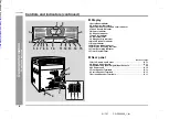
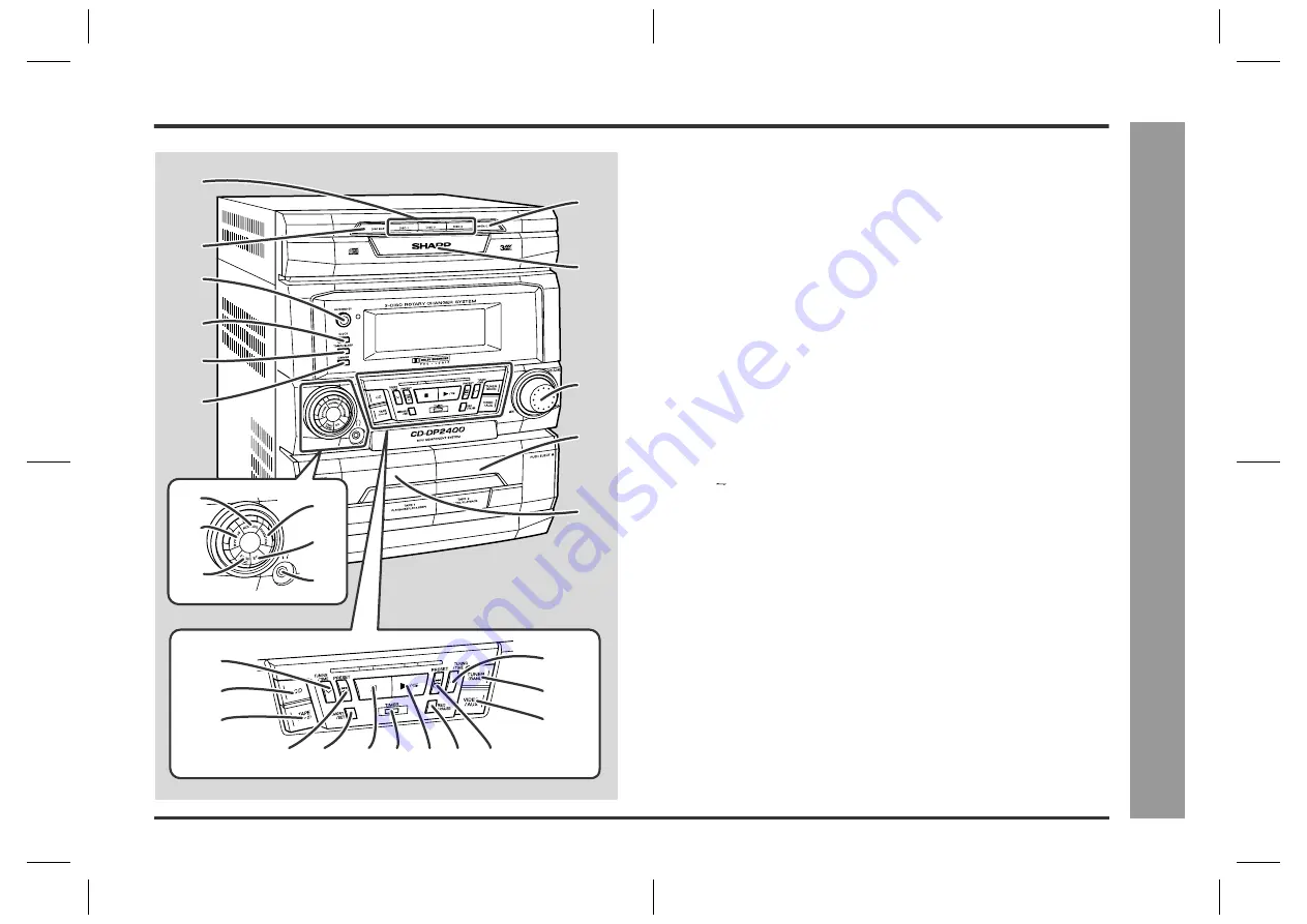
Controls and indicators

"

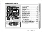
Front panel

Reference page

1. Disc Number Select Buttons  . . . . . . . . . . . . . . . . . . . . . . . . . . . . . . 15
2. Disc Skip Button  . . . . . . . . . . . . . . . . . . . . . . . . . . . . . . . . . . . . . . . . 15
3. On/Stand-by Button   . . . . . . . . . . . . . . . . . . . . . . . . . . . . . . . . . . . . . 13
4. Clock Button   . . . . . . . . . . . . . . . . . . . . . . . . . . . . . . . . . . . . . . . . 14, 24
5. Timer/Sleep Button  . . . . . . . . . . . . . . . . . . . . . . . . . . . . . . . . . . . 24, 25
6. Dimmer Button   . . . . . . . . . . . . . . . . . . . . . . . . . . . . . . . . . . . . . . . . . 13
7. Disc Tray Open/Close Button  . . . . . . . . . . . . . . . . . . . . . . . . . . . . . . 15
8. Disc Tray   . . . . . . . . . . . . . . . . . . . . . . . . . . . . . . . . . . . . . . . . . . . . . . 15
9. Volume Control   . . . . . . . . . . . . . . . . . . . . . . . . . . . . . . . . . . . . . . . . . 13

10.Tape 2 Cassette Compartment . . . . . . . . . . . . . . . . . . . . . . . . . . 21, 23 
11.Tape 1 Cassette Compartment . . . . . . . . . . . . . . . . . . . . . . . . . . 21, 23 
12.Normal Button (with Indicator)   . . . . . . . . . . . . . . . . . . . . . . . . . . . . 27
13.Bypass Button (with Indicator)   . . . . . . . . . . . . . . . . . . . . . . . . . . . . 27
14.Extra Bass/Demo Mode Button  . . . . . . . . . . . . . . . . . . . . . . . . . . . . 13
15.Phantom Button (with Indicator)  . . . . . . . . . . . . . . . . . . . . . . . . . . . 27
16.Equaliser Mode Select Button  . . . . . . . . . . . . . . . . . . . . . . . . . . . . . 13
17.Headphone Socket   . . . . . . . . . . . . . . . . . . . . . . . . . . . . . . . . . . . . . . 26
18.Tuning and Time Down Button  . . . . . . . . . . . . . . . . . . . . . . . . . 14, 19
19.CD Button   . . . . . . . . . . . . . . . . . . . . . . . . . . . . . . . . . . . . . . . . . . 15, 22
20.Tape (1   2) Button  . . . . . . . . . . . . . . . . . . . . . . . . . . . . . . . . . . . 21, 23
21.Tuning and Time Up Button  . . . . . . . . . . . . . . . . . . . . . . . . . . . . 14, 19
22.Tuner (Band) Button  . . . . . . . . . . . . . . . . . . . . . . . . . . . . . . . . . . . . . 19
23.Video/Auxiliary Button  . . . . . . . . . . . . . . . . . . . . . . . . . . . . . . . . . . . 26
24.CD Track Down or Fast Reverse, Tape 2 Rewind, 

Tuner Preset Down Button  . . . . . . . . . . . . . . . . . . . . . . . . . . 16, 20, 21

25.Memory/Set Button  . . . . . . . . . . . . . . . . . . . . . . . . . . . . . . . . 14, 18, 20
26.CD or Tape Stop Button (with Indicator)  . . . . . . . . . . . . . . . . . . 16, 21
27.Timer Set Indicator  . . . . . . . . . . . . . . . . . . . . . . . . . . . . . . . . . . . . . . 25
28.CD Play or Repeat, Tape Play Button (with Indicator)  . . . . 16, 17, 21
29.Tape 2 Record Pause Button  . . . . . . . . . . . . . . . . . . . . . . . . . . . 22, 23
30.CD Track Up or Fast Forward, Tape 2 Fast Forward, 

Tuner Preset Up Button   . . . . . . . . . . . . . . . . . . . . . . . . . . . . 16, 20, 21

1

7

8

9

10

11

2

3

4

5

6

18

21

22
23

19
20

24 25 26 27 28 29 30

12

15

16

17

13

14

Downloaded from: 

http://www.usersmanualguide.com/

Summary of Contents for CD-DP2400E

Page 1: ...it CP DP2400E front speakers GBOXS0107AWM1 cen tre speaker and GBOXS0108AWM1 surround speakers MINI COMPONENT SYSTEM MODEL CD DP2400E OPERATION MANUAL If you require any advice or assistance regarding your Sharp product please visit our web site www sharp co uk support Customers without Internet access may telephone 08705 274277 during office hours or 01 676 0648 if telephoning from Ireland 0101 D...

Page 2: ...e with the following code Blue Neutral Brown Live As the colours of the wires in the mains lead of this product may not correspond with the coloured markings identifying the terminals in your plug proceed as follows The wire which is coloured blue must be connected to the plug terminal which is marked N or coloured black The wire which is coloured brown must be connected to the plug terminal which...

Page 3: ...ning to the radio 19 Listening to the memorised station 20 Tape Playback Listening to a cassette tape TAPE 1 or TAPE 2 21 Tape Recording Recording to a cassette tape 22 23 Advanced Features Timer and sleep operation 24 25 Enhancing your system 26 Enjoy surround sound 27 28 References Troubleshooting chart 29 30 Maintenance 30 Specifications 31 TERMS OF GUARANTEE Back cover Accessories Please confi...

Page 4: ...ied on this unit Using this product with a higher voltage other than that which is specified is dangerous and may result in a fire or other type of accident causing damage SHARP will not be held responsible for any damage resulting from use of this unit with a voltage other than that which is specified Volume control The sound level at a given volume setting depends on speaker efficiency location ...

Page 5: ...on with Indicator 27 16 Equaliser Mode Select Button 13 17 Headphone Socket 26 18 Tuning and Time Down Button 14 19 19 CD Button 15 22 20 Tape 1 2 Button 21 23 21 Tuning and Time Up Button 14 19 22 Tuner Band Button 19 23 Video Auxiliary Button 26 24 CD Track Down or Fast Reverse Tape 2 Rewind Tuner Preset Down Button 16 20 21 25 Memory Set Button 14 18 20 26 CD or Tape Stop Button with Indicator ...

Page 6: ...t Play Indicator 10 Music Schedule Indicator 11 Sleep Indicator 12 FM Stereo Mode Indicator 13 FM Stereo Receiving Indicator 14 Timer Recording Indicator 15 Timer Play Indicator Rear panel Reference page 1 FM 75 Ohms Aerial Socket 10 11 2 AM Loop Aerial Socket 10 11 3 Video Auxiliary Audio Signal Input Sockets 26 4 AC Power Lead 10 12 5 Front Speaker Terminals 10 11 6 Centre Speaker Terminals 10 1...

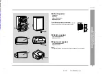
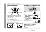
Page 7: ...Full Range Speaker 2 Speaker Wire Surround speaker 1 Full Range Speaker 2 Speaker Wire Note The speaker grilles on the centre and surround speakers are not removable 3 4 1 2 3 1 2 1 2 Front speaker grilles are removable Make sure nothing comes into contact with the speaker diaphragms when you remove the speaker grilles Downloaded from http www usersmanualguide com ...

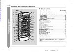
Page 8: ...aliser Mode Select Button 13 14 Tape 2 Record Pause Button 22 23 15 CD Button 15 22 16 On Stand by Button 9 17 Tuner Band Button 19 18 Tuner Preset Up and Down Buttons 20 19 CD Stop Button 16 20 CD Play or Repeat Button 16 17 21 CD Track Up or Fast Forward Button 16 22 CD Random Button 17 23 Tape 2 Play Button 21 24 Disc Skip Button 15 25 Tape 2 Fast Forward Button 21 26 Tape 2 Rewind Button 21 27...

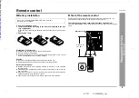
Page 9: ...nit with a soft cloth Exposing the sensor on the unit to strong light may interfere with operation Change the lighting or the direction of the unit Keep the remote control away from moisture heat shock and vibrations Test of the remote control Check the remote control after checking all the connections see pages 10 12 Point the remote control directly at the remote sensor on the unit The remote co...

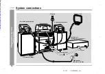
Page 10: ...ctions System connections AM loop aerial Front speaker Right Front speaker Left Surround speaker Right Surround speaker Left VCR DVD etc not supplied see page 26 FM aerial Centre speaker Wall socket AC 230 V 50 Hz not supplied Downloaded from http www usersmanualguide com ...

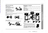
Page 11: ...re in the direction where the strongest signal can be received Supplied AM loop aerial Connect the AM loop aerial wire to the AM LOOP socket Position the AM loop aerial for optimum reception Place the AM loop aerial on a shelf etc or attach it to a stand or a wall with screws not supplied Assembling Attaching to the wall Wall Screws not supplied External FM aerial If you use other speakers with im...

Page 12: ...ome colour variation may occur depending on the type of TV used If colour variation occurs Turn off the TV from the power switch After 15 30 minutes turn the TV on again If the colour variation is still present Move the front speakers further away from the TV If any kind of magnet or an electromagnet is placed too close to the TV and the sys tem irregular colours may appear on the TV screen Main u...

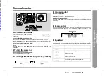
Page 13: ...ckwise the volume will increase When it is turned anti clockwise the volume will decrease Remote control operation Press the VOLUME button to increase the volume and the VOLUME button for decreasing Bass control When the power is first turned on the unit will enter the extra bass mode which emphasises the bass frequencies and X BASS will appear To cancel the extra bass mode press the X BASS DEMO X...

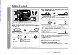
Page 14: ... AM 0 00 PM 11 59 Note that this can only be set when the unit is first installed or it has been reset Refer to Clearing all the memory reset on page 30 for details 4 Press the TUNING TIME or button to adjust the hour and then press the MEMORY SET button Press the TUNING TIME or button once to advance the time by 1 hour Hold it down to advance continuously When the 12 hour display is selected AM w...

Page 15: ...n the open position CDs can be placed on any open position on the disc tray Be sure to place an 8 cm 3 CD s in the middle of the disc positions 5 Press the OPEN CLOSE button to close the disc tray Music schedule Total number of tracks on the CD whose number is flashing Total playing time of the CD whose number is flashing The music schedule will display only the number of tracks on the disc If the...

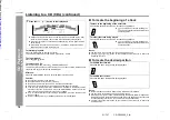
Page 16: ...lows you to locate the beginning of a track To locate the desired portion Notes Normal playback will resume when the or button is released You can locate the desired portion on a single disc only When the end of the last track is reached during fast forward END will appear on the display and CD operation will be paused When the beginning of the first track is reached during fast reverse the unit w...

Page 17: ... you can move to the track selected next by the random operation On the other hand the button does not allow you to move to the previous track The beginning of the track being played will be located In random play the CD player will select and play tracks automatically You cannot select the order of the tracks Caution After performing repeat or random play be sure to press the CD button Other wise...

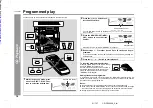
Page 18: ...top mode press one of the DISC 1 DISC 3 but tons to select the desired disc Selected disc number 2 Press the or button to se lect the desired track Selected track number You can also select a track by pressing the or button on the remote control 3 Press the MEMORY SET MEM ORY button to save the track number Playback order When the track is memorised MEMORY will appear 4 Repeat steps 1 3 for other ...

Page 19: ...ER BAND button repeatedly to select the desired frequency band FM or AM 3 Press the TUNING TIME or button to tune in to the desired station Manual tuning Press the TUNING TIME button as many times as required to tune in to the de sired station Auto tuning When the TUNING TIME button is pressed for more than 0 5 seconds scanning will start automatically and the tuner will stop at the first receivab...

Page 20: ...rder starting with preset channel 1 4 Within 30 seconds press the MEMORY SET button to store that station in memory If the MEMORY and preset number indicators go out before the station is mem orised repeat the operation from step 2 5 Repeat steps 1 4 to set other stations or to change a preset sta tion When a new station is stored in memory the station previously memorised will be erased Press the...

Page 21: ...r low noise tapes for the best sound Metal or CrO tapes are not recommended Do not use C 120 tapes or poor quality tapes as they may cause mal functions Before loading a tape into the cassette compartment tighten the slack with a pen or a pencil 1 Press the ON STAND BY button to turn the power on 2 Open the cassette door by pushing the area marked PUSH EJ ECT 3 Load a cassette into the TAPE 1 or T...

Page 22: ...cording from the beginning of the interrupted track turn over the tape press the REC PAUSE button and then the TAPE 2 button If tracks have been stored in memory using the programmed recording recording will restart from the first track stored in memory 1 Press the ON STAND BY button to turn the power on 2 Load a cassette into the TAPE 2 cassette compartment with the side to be recorded on facing ...

Page 23: ...ecording on a cassette tape make sure that the erase prevention tabs are not removed Cassettes have removable tabs that prevent accidental recording or erasing To protect the recorded sound remove the tab after recording Cover the tab hole with the adhesive tape to record on the tape with out the tab Tab for side B Tab for side A Side A 1 Press the ON STAND BY button to turn the power on 2 Load a ...

Page 24: ...or timer recording Load a cassette for recording in the TAPE 2 cassette compartment 1 Press the ON STAND BY button to turn the power on 2 Press the CD TUNER BAND or TAPE 1 2 button to select the desired function To select the timer playback source CD TUNER BAND or TAPE 1 2 To select the timer recording source TUNER BAND If you select TUNER BAND tune in to the desired station 3 Adjust the volume us...

Page 25: ...If you select TUNER it will enter the stand by mode one hour after the tim er playback starts In timer recording When the recording tape reaches its end the timer recording will end and the unit will enter the stand by mode Once the time is set the setting will be retained until a new time is entered When performing timer playback or recording using another unit connected to the VIDEO AUX sockets ...

Page 26: ...commended impedance is 32 ohms Plugging in the headphones disconnects the speakers automatically Adjust the volume using the VOLUME control VCR DVD etc To the line output sockets Red RCA lead not supplied White Red White 1 Use a connection lead to connect the VCR DVD etc to the VIDEO AUX sockets When using video equipment connect the audio output to this unit and the video output to a television 2...

Page 27: ...Dolby Pro Logic This mode is memo rised until a new mode is selected Centre speaker Normal mode Phantom mode Front speaker Left Front speaker Right Surround speaker Right Surround speaker Left Front speaker Left Front speaker Right Surround speaker Right Surround speaker Left 1 Connect the equipment you want to play see page 26 2 Press the VIDEO AUX button 3 Press the DOLBY PRO LOGIC button on the...

Page 28: ...each speaker in order at about 2 second inter vals In normal mode In phantom mode Left L ch Centre C ch Right R ch Surround S ch Left L ch Right R ch Surround S ch 2 Adjust the speaker volume level whilst the test tone is being out put from the centre or surround speakers To set the centre speaker volume to the level of the front speakers When in the normal mode press the CENTER LEVEL button to in...

Page 29: ...pped or stopped in the middle of a track Is the unit located near excessive vibra tions Is the disc very dirty Has condensation formed inside the unit Symptom Possible cause The radio makes unusual noises continuously Is the unit placed near the TV or compu ter Is the FM aerial or AM loop aerial placed properly Move the AC power lead away from the aerial if located near Symptom Possible cause Cann...

Page 30: ...se poor sound and tape jams Clean these parts with a cotton swab moistened with a commercial head pinch roller cleaner or isopropyl alcohol When cleaning the heads pinch rollers etc unplug the unit which contains high voltages After long use the deck s heads and capstans may become magnetised causing poor sound Demagnetise these parts once every 30 hours of playing recording time by using a commer...

Page 31: ...es 16 50 ohms recommended 32 ohms Input terminals Video Auxiliary audio signal 500 mV 47 kohms Type 3 disc multi play compact disc player Signal readout Non contact 3 beam semiconductor laser pickup D A converter 1 bit D A converter Frequency response 20 20 000 Hz Dynamic range 90 dB 1 kHz Frequency range FM 87 5 108 MHz AM 522 1 620 kHz Frequency response 50 14 000 Hz normal tape Signal noise rat...

Page 32: ... be provided 4 The guarantee does not cover carriage costs jewelled styli audio tapes compact discs or batter ies 5 In the unlikely event of this product requiring repair please contact the supplier from whom it was purchased Where this is not possible please contact the Sharp Customer Information Centre on the telephone number given below 6 No person has any authority to vary the terms or conditi...

Page 33: ... tv dvd and othes Manual users user manuals user guide manual owners manual instruction manual manual owner manual owner s manual guide manual operation operating manual user s manual operating instructions manual operators manual operator manual product documentation manual user maintenance brochure user reference pdf manual Downloaded from http www usersmanualguide com ...

Reviews: