background image

R-480J

37

1

A

B

C

D

E

F

G

H

A

B

C

D

E

F

G

H

2

3

4

5

6

1

2

3

4

5

6

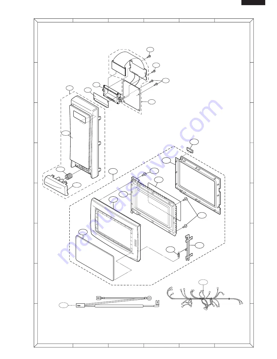
CONTROL PANEL PARTS

DOOR PARTS

Actual wire harness may be different from illustration.

6-2

4-18

5-4

5-8

5-8

5-5

5-6

5-1

5-7

5-3

5-2

5

3-1

3-5 

3-5

3-5

3-2

3-3

3-4

3-2-1

3-2-3

3-2-2

6-1

MISCELLANEOUS

Summary of Contents for Carousel R-480J

Page 1: ... CONTROL PANEL 16 COMPONENT REPLACEMENT AND ADJUSTMENT PROCEDURE 22 MICROWAVE MEASUREMENT 28 WIRING DIAGRAM 29 PICTORIAL DIAGRAM 30 POWER UNIT CIRCUIT 31 CPU UNIT CIRCUIT 32 PRINTED WIRING BOARD 33 PARTS LIST 34 S8406R480JPJ MICROWAVE OVEN MODEL R 480J In interests of user safety the oven should be restored to its original condition and only parts identical to those specified should be used SHARP ...

Page 2: ...R 480J ...

Page 3: ... load attached Never look into an open waveguide or antenna while the device is energized WARNING Never operate the oven until the following points are ensured A The door is tightly closed B The door brackets and hinges are not defective C The door packing is not damaged D The door is not deformed or warped E There is not any other visible damage with the oven Servicing and repair work must be car...

Page 4: ... Variable Cooking Repetition Rate HIGH Full power throughout the cooking time MEDIUM HIGH approx 70 of Full Power MEDIUM approx 50 of Full Power MEDIUM LOW approx 30 of Full Power LOW approx 10 of Full Power HELP pad SENSOR REHEAT pad SENSOR COOK pads HEALTHY MENU pads EXPRESS MENUS pads EASY DEFROST pad MORE LESS pads QUICK EASY pad NUMBER pads POWER LEVEL pad CLOCK pad TIMER pad STOP CLEAR pad I...

Page 5: ...icrowave power setting If not pressed HIGH is auto matically selected INSTANT COOK START PAD Press once to cook for 1 minute on HIGH or increase by 1 minute multi ples each time this pad is pressed during cooking Press to start the oven after setting programmes SENSOR COOK PADS Press to select Sensor Cook menus QUICK AND EASY PAD Press to select Quick and Easy menus EASY DEFROST PAD Press to defro...

Page 6: ...ut 3 3 volts A C output on the filament winding and high voltage of approximately 2000 volts A C on the secondary winding 2 The filament winding voltage 3 3 volts heats the magnetron filament and the high voltage 2000 volts is sent to the voltage doubling circuit where it is doubled to negative voltage of approximately 4000 volts D C 3 The 2450 MHz microwave energy produced in the magnetron genera...

Page 7: ...er is turned on microwave energy is produced and first stage is started The 16 seconds is the cooling time required to remove any vapor from the oven cavity and sensor NOTE During this first stage do not open the door or touch STOP CLEAR pad 4 When the sensor detects the vapor emitted from the food the display switches over to the remaining cooking time and the timer counts down to zero At this ti...

Page 8: ...mal cut out located on the top of the oven cavity is designed to prevent damage to the oven if the foods in the oven catch fire due to over heating produced by improper setting of cook time or failure of control unit Under normal operation the oven thermal cut out remains closed However when abnormally high temperature is reached within the oven cavity the oven thermal cut out will open at 145 C c...

Page 9: ...cks and reconnect the leads to the primary of the power trans former WARNING TO SERVICE PERSONNEL REMEMBER TO CHECK 4R 1 Reconnect all leads removed from components during testing 2 Replace the outer case cabinet 3 Reconnect the supply 4 Run the oven Check all functions Microwave ovens should not be run empty To test for the presence of microwave energy within a cavity place a cup of cold water on...

Page 10: ...erates properly at HIGH and when the STOP CLEAR pad is touched the oven stops Oven goes into cook cycle but shuts down before end of cooking cycle Oven stops as soon as when the START pad is touched AH sensor does not end during Sensor Cooking condition Oven does not shut off after a cup of water is boiling by sensor cooking Oven stops at 16 sec after starting MAGNETRON POWER TRANSFORMER H V RECTI...

Page 11: ...follows Room temperature T0 around 20 C Power supply Voltage Rated voltage Water load 1000 g Initial temperature T1 10 1 C Heating time 35 sec Mass of container mc 330 g T2 Final Temperature T T2 T1 P 120 x T 0 55 x mc T2 T0 35 Measuring condition 1 Container The water container must be a cylindrical borosilicate glass vessel having a maximum material thickness of 3 mm and an outside diameter of a...

Page 12: ...prox 1 0 Ω b Secondary winding approx 84 Ω c Filament winding less than 1Ω If the reading obtained are not stated as above then the power transformer is probably faulty and should be replaced CARRY OUT 4R CHECKS C HIGH VOLTAGE RECTIFIER ASSEMBLY TEST HIGH VOLTAGE RECTIFIER TEST CARRY OUT 3D CHECKS Isolate the high voltage rectifier assembly from the HV circuit The high voltage rectifier can be tes...

Page 13: ...ECKS Disconnect the leads from the terminals of the noise filter Using an ohmmeter check between the terminals as de scribed in the following table MEASURING POINT INDICATION OF OHMMETER Between N and L Open circuit Between terminal N and WHITE Short circuit Between terminal L and RED Short circuit If incorrect readings are obtained replace the noise filter unit CARRY OUT 4R CHECKS CARRY OUT 3D CH...

Page 14: ...ter and ohmmeter In this service manual the touch control panel assembly is divided into two units Control Unit and Key Unit and also the Control Unit is divided into two units CPU Unit and Power Unit and troubleshooting by unit replacement is described according to the symptoms indicated 1 Key Unit Note Check key unit ribbon connection before replacement The following symptoms indicate a defectiv...

Page 15: ... does not respond it is faulty and must be replaced If a specific pad does not respond the above method may be used after clearing the control unit to determine if the control unit or key pad is at fault CARRY OUT 3D CHECKS M RELAY TEST Remove the outer case and check voltage between Pin No 1 of the 2 pin connector A and the normal open terminal of the relay RY1 on the power unit with an A C voltm...

Page 16: ...iliters 7 2 oz of tap water in a 1000 milliliter measuring cup 2 Place the container on the center of tray in the oven cavity 3 Close the door 4 Touch the CLOCK once the POWER LEVEL pad twice the START pad once the number pad 1 once and the number pad 4 once Now the oven is in the sensor cooking condition and AH20 SENSOR and COOK will appear in the display 5 The oven will operate for the first 16 ...

Page 17: ...nnect the dummy resistor circuit see fig to the sensor connector of control panel 6 Disconnect the leads to the primary of the power transformer 7 Ensure that these leads remain isolated from other components and oven chassis by using insulation tape 8 After that procedure re connect the power supply cord 9 Check the sensor cook operation proceed as follows 9 1 Touch the CLOCK pad once the POWER L...

Page 18: ...2 Indicator Circuit This circuit consists of 40 segments and 16 common electrodes using a Liquid Crystal Display 3 Power Source Circuit This circuit generates voltages necessary in the con trol unit from the AC line voltage In addition the synchronizing signal is available in order to compose a basic standard time in the clock circuit Symbol Voltage Application VC 5V LSI IC1 4 Relay Circuit A circ...

Page 19: ...gnal 5V 28 P46 OUT Terminal not used 29 P45 OUT Oven lamp fan motor and turntable motor driving signal To turn on and off shut off relay RY1 The square waveform voltage is delivered to the RY1 driving circuit and RY2 control circuit 30 P44 OUT Magnetron high voltage circuit driving signal To turn on and off the cook relay RY2 The signals holds L level during microwave cook ing and H level while no...

Page 20: ...nput into P15 46 P14 IN Signal similar to P17 When either G12 line on key matrix is touched a corresponding signal will be input into P14 47 AIN7 IN Signal similar to P17 When either G13 line on key matrix is touched a corresponding signal will be input into AIN7 48 AIN6 IN Input terminal to judge the model The signal out of P04 will be input into AIN6 through G4 line on key matrix The LSI will ju...

Page 21: ... not used 103 142 SEG39 SEG0 OUT Segment data signal Connected to LCD The relation between signals and LCD are as follows LSI signal Pin No LCD segment LSI signal Pin No LCD segment SEG 39 103 SEG 1 SEG 19 123 SEG 21 SEG 38 104 SEG 2 SEG 18 124 SEG 22 SEG 37 105 SEG 3 SEG 17 125 SEG 23 SEG 36 106 SEG 4 SEG 16 126 SEG 24 SEG 35 107 SEG 5 SEG 15 127 SEG 25 SEG 34 108 SEG 6 SEG 14 128 SEG 26 SEG 33 1...

Page 22: ...lute humidity circuit to allow the LSI to control sensor cooking of the unit When the unit is set in the sensor cooking mode 16 seconds clearing cycle occurs than the detector circuit starts to function and the LSI observes the initial voltage available at its AIN5 terminal With this voltage given the switches SW1 to SW5 in the LSI are turned on in such a way as to change the resistance values in ...

Page 23: ...nnected to the oven B On some models the power supply cord between the touch control panel and the oven proper is long enough that they may be separated from each other For those models therefore it is possible to check and repair the controls of the touch control panel while keeping it apart from the oven proper in this case you must short both ends of the door sensing switch on PWB of the touch ...

Page 24: ...ransformer High voltage capacitor High voltage rectifier assembly and High voltage fuse 2 Hot parts Oven lamp Magnetron High voltage transformer and Oven cavity 3 Sharp edge Bottom plate Oven cavity Waveguide flange Chassis support and other metallic plate 4 Movable parts to prevent a fault Fan blade Fan motor Switch Switch lever Open button 3 Do not catch the wire leads in the outer case cabinet ...

Page 25: ...er 11 Disconnect the high voltage rectifier assembly from capacitor 12 Now capacitor and rectifier assembly are free CAUTION WHEN REPLACING HIGH VOLTAGE REC TIFIER AND HIGH VOLTAGE CAPACITOR GROUND SIDE TERMINAL OF THE HIGH VOLTAGE RECTIFIER MUST BE SECURED FIRMLY WITH A GROUNDING SCREW HIGH VOLTAGE RECTIFIER ASSEMBLY AND HIGH VOLTAGE CAPACITOR REMOVAL TURNTABLE MOTOR REMOVAL 1 Disconnect oven fro...

Page 26: ...2 Disconnect the wire leads from the fan motor 3 Remove the fan duct from the oven cavity 4 Remove two 2 screws holding the fan motor to the back plate of the oven cavity 5 Remove the fan blade from the fan motor shaft according to the following procedure 1 Hold the edge of the rotor of the fan motor by using a pair of grove joint pliers CAUTION Make sure that any pieces do not enter the gap betwe...

Page 27: ...with two 2 mounting screws to oven flange 4 Make sure that the monitor switch is operating properly and check continuity of the monitor circuit Refer to chapter Test Procedure and Adjustment procedure 1ST LATCH SWITCH 2ND INTERLOCK RELAY CONTROL SWITCH AND MONITOR SWITCH REMOVAL 1ST LATCH SWITCH 2ND INTERLOCK RELAY CONTROL SWITCH AND MONITOR SWITCH ADJUSTMENT If the 1st latch switch 2nd interlock ...

Page 28: ...and remove it from door frame with releasing latch spring from door frame and latch head 13 Now latch head and latch spring are free 14 Remove the three 3 screws holding the door panel to the door frame 15 Release door panel from nine 9 tabs of door frame by sliding door panel downward 16 Now door panel with sealer film is free 17 Tear sealer film from door panel 18 Now door panel is free 19 Remov...

Page 29: ...gnment from horizontal line of cavity face plate is to be less than 1 0mm 3 Door is positioned with its face pressed toward cavity face plate 4 Check for microwave leakage around door with an approvedmicrowavesurveymeter RefertoMicrowave Measurement Procedure Note The door on a microwave oven is designed to act as an electronic seal preventing the leakage of microwave energy from oven cavity durin...

Page 30: ... microwave ovens must be used for testing Recommended instruments are NARDA 8100 NARDA 8200 HOLADAY HI 1500 SIMPSON 380M 2 Place the oven tray into the oven cavity 3 Place the load of 275 15ml of water initially at 20 5 C in the centre of the oven tray The water container should be a low form of 600 ml beaker with inside diameter of approx 8 5cm and made of an electrically non conductive material ...

Page 31: ...VEN THERMAL CUT OUT 145 C MAGNETRON RY 2 EARTH BLU BRN 230 240V 50Hz G Y FUSE F10A N L LINE CROSS CAPACITOR 0 068µ AC250V NOISE SUPPRESSION COIL LINE BYPASS CAPACITOR 0 0022µ AC250V LINE BYPASS CAPACITOR 0 0022µ AC250V F1 F2 F3 AH SENSOR 2ND INTERLOCK RELAY EARTH BLU BRN 230 240V 50Hz G Y FUSE F10A N L LINE CROSS CAPACITOR 0 068µ AC250V NOISE SUPPRESSION COIL LINE BYPASS CAPACITOR 0 0022µ AC250V L...

Page 32: ...1 CN A GRN RED 2 1 CN B BLU BRN POWER SUPPLY CORD EARTH NEUTRAL LIVE G Y N L WHT RED M10A CONTROL PANEL RY1 N O N O COM COM RY2 CN A CN B T1 1 1 2 2 CPU UNIT POWER UNIT CN F CN C CN G RED ORG ORG W H T OVEN LAMP AND SOCKET BLACK MARK NOTE Neutral WHT wire must be connected to the terminal with black mark on the oven light socket ORG WHT ORG RED THERMAL CUT OUT MAGNETRON BLK H V RECTIFIER H V FUSE ...

Page 33: ...C4 10µ 35v R1 2 4k 1SS270A 1SS270A D1 D4 1N4002 D6 R5 4 7k R2 680 1 2w R3 510 1 2w R6 3 3k Q2 2SB1238 SP1 PKM22EPT Q1 2SB1238 RY1 RY2 Q3 KRC243M CN C 12PIN LEAD WIRE HARNESS LED GND VC VA INT VR BUZZER MICRO NC NC OVEN LAMP TURNTABLE MOTOR FAN MOTOR AC AC MICRO 2ND INTERLOCK RELAY CONTROL SWITCH 2ND INTERLOCK RELAY CONTROL SWITCH OVEN LAMP TURNTABLE MOTOR FAN MOTOR C10 C 2 C 3 C 1 C 4 C 9 C 5 C 6 ...

Page 34: ... NC C17 MA152WA C 10 C 9 5 0 4 9 3 8 2 7 1 6 MORE STOP CLEAR CLOCK TIMER INSTANT COOK START LESS HELP NOTE IF NOT SPECIFIED 1 10W 5 CN F AH SENSOR BA4558 LOW FAT MEALS DESSERTS VEGETABLES EASY DEFROST EXPRESS MEAL SENSOR REHEAT EXPRESS COOK VEGETARIAN MEALS POWER LEVEL RICE PASTA CN G QUICK EASY EXPRESS DEFROST C60 C65 330PF 50V X 6 R74 R79 270K X 6 R68 R73 15K X 6 C15 C18 COM5 COM4 COM3 COM2 COM1...

Page 35: ... Printed Wiring Board WH 1 SH B SH A 1 C3 C4 C5 R3 C2 F C1 10 D4 D2 D1 D3 D9 D10 RY3 CN D D8 ZD1 VRB D U R2 R1 R6 R5 SP1 3 E B D6 D5 Q2 R4 2 6 11 P S RY2 T1 AC VRS1 QKITPB026MRE0 5 D7 OMIF D U 9 8 7 E Q1 B 4 E RY1 AC OL TTM FM B Q3 CN C CN C CN B CN A 1 1 9 12 1 1 1 2 XA VH 2 2 ...

Page 36: ...tron 1 BF 1 16 QFS IA010WRZZ H V fuse 0 80A 1 AQ 1 17 FDTCTA214WRKZ AH sensor assembly 1 AX CABINET PARTS 2 1 GCABUA711WRP0 Outer case cabinet 1 BC 2 2 FDAI A225WRYZ Bottom plate 1 BB 2 3 GLEGPA074WRE0 Foot 4 AC CONTROL PANEL PARTS 3 1 DPWBFC436WRKZ Control unit assembly 1 BG 3 2 DPNLCB907WRKZ Control panel frame with key unit 1 BB 3 2 1 FUNTKB154WREZ Key unit 1 AX 3 2 2 JBTN B104WRF0 Open button ...

Page 37: ...peration manual 1 AP 6 7 NTNT A108WREZ Turntable tray 1 AW SCREWS NUTS AND WASHERS 7 1 XHTSD40P08RV0 Screw M4 x 8 9 AA 7 2 LX CZ0052WRE0 Special screw 2 AA 7 3 LX EZA042WRE0 Special screw 2 AB 7 4 XHPSD30P06000 Screw M3 x 6 4 AA 7 5 XHPSD40P08K00 Screw M4 x 8 5 AA 7 6 XHPSD40P08000 Screw M4 x 8 4 AA 7 7 LX EZA050WRE0 Special screw 1 AB 7 8 XOTSD40P12RV0 Screw M4 x 12 12 AB 7 9 XOTSD40P08000 Screw ...

Page 38: ...1 6 7 1 5 4 5 4 20 7 1 4 11 7 1 7 4 7 1 4 6 7 6 1 15 7 2 4 9 1 13 7 5 4 1 4 7 1 9 4 4 1 3 1 4 1 3 1 14 1 1 1 11 1 12 7 9 2 3 7 8 2 2 4 15 7 8 2 3 2 3 6 4 4 19 7 1 1 7 1 8 7 1 4 16 4 2 4 17 A A 4 3 1 16 7 5 4 12 4 21 4 10 6 5 1 6 7 7 7 5 1 10 1 2 7 5 7 8 7 1 7 8 7 8 4 14 4 13 7 1 7 3 7 1 7 4 1 17 4 22 4 8 6 3 ...

Page 39: ...B C D E F G H 2 3 4 5 6 1 2 3 4 5 6 CONTROL PANEL PARTS DOOR PARTS Actual wire harness may be different from illustration 6 2 4 18 5 4 5 8 5 8 5 5 5 6 5 1 5 7 5 3 5 2 5 3 1 3 5 3 5 3 5 3 2 3 3 3 4 3 2 1 3 2 3 3 2 2 6 1 MISCELLANEOUS ...

Page 40: ...CORPORATION ALL RIGHTS RESERVED No part of this publication may be reproduced stored in retrieval systems or transmitted in any form or by any means electronic mechanical photocopying recording or otherwise without prior written permission of the publisher ...

Reviews: