46
AK - 45
CHASSIS
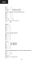
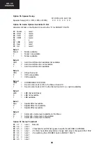
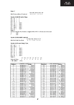
Option 55. Speaker Setup
b7 b6 b5 b4 b3 b2 b1 b0
Speaker Setup (L/R, L/C/R, L/R/S, L/C/R/S)
0 0 0 0 0 0 0 0
Option 56. Audio Options Available Or Not
Attention: All bits on the Option 56 must be the “0” for MONO TV SETS
B7: Nicam = note 7
B6: ASD
= note 6
B5: VRS
= note 5
B4: CRM
= note 4
B3: …
= x
B2: LBE
= note 2
B1: Spa
= note 1
B0: Avl
= note 0
Note 7:
Nicam
=
Nicam available
0
=
Nicam not available
1 = Nicam
available
Note 6:
ASD
=
Auto Sound Detection available/not available
0
=
Auto Sound Detection not available
1
=
Auto Sound Detection available
Note 5:
VRS
=
Virtual Surround
0
=
VRS not available
1 = VRS
available
Note 4:
CRM
=
CARRIER MUTE OFF/ON
0
=
Sound carrier mute is ON in the Stereo Sound IC
1
=
Sound carrier mute is OFF in the Stereo Sound IC (i.e. option available)
Note 2:
LBE
=
LBE (Dynamic Bass)
0
=
LBE not available
1 = LBE
available
Note 1:
Spa
=
Spatial Effect available
0
=
Spatial Effect not available
1
=
Spatial Effect available
Note 0:
Avl
=
Automatic volume level available on the Menu
0
=
Automatic volume level not available
1
=
Automatic volume level available
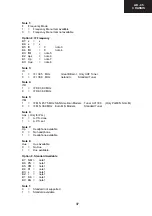
Option 57. Stereo Threshold
B7: b7 =
note 1
Remark:
B6: b6 = note 1
B5: b5 =
note 1
-Threshold for all FM A2 signals to switch from MONO to STEREO.
B4: b4 =
note 1
-For first check after programme change half value is changed (0Ch) 19h/2
B3: b3 =
note 1
-For switching from STEREO back to MONO: 19h/4 *3
B2: b2 = note 1
B1: b1 = note 1
B0: b0 = note 1
Summary of Contents for C-2890EES
Page 7: ...7 C 2890EES CHASSIS LAYOUT Mother Unit CRT Unit Control Panel Unit ...
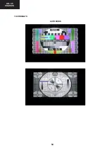
Page 69: ...53 AK 45 CHASSIS 14 6 GEOMETRY ADJUSTMENT 4 3 FORMATS 4 3 MODE 16 9 MODE ...
Page 70: ...54 AK 45 CHASSIS 16 9 FORMATS AUTO MODE ...
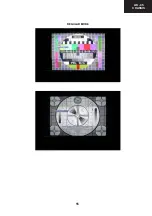
Page 71: ...55 AK 45 CHASSIS REGULAR MODE ...
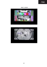
Page 72: ...56 AK 45 CHASSIS ZOOM 14 9 MODE ...
Page 73: ...57 AK 45 CHASSIS ZOOM 16 9 MODE ...
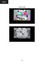
Page 74: ...58 AK 45 CHASSIS SUBTITLE ZOOM MODE ...
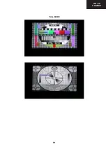
Page 75: ...59 AK 45 CHASSIS FULL MODE ...
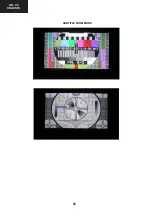
Page 76: ...60 AK 45 CHASSIS PANORAMIC MODE ...
Page 86: ...70 AK 45 CHASSIS 1 I H G F E D C B A 2 3 4 5 6 7 16 7 Schematic Diagram of CRT Socket Circuit ...
Page 91: ...75 AK 45 CHASSIS Notes ...

