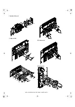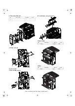
AR-FN6 BLOCK DIAGRAM, WIRING DIAGRAM-1
[9] BLOCK DIAGRAM, WIRING DIAGRAM
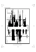
1. BLOCK DIAGRAM
Staple Unit Motor
AR-FN6
Elevator Motor
Paper Push Solenoid
Staple Compiler Gate Solenoid
Finisher Gate Solenoid
Tray2 Solenoid
Stopper Solenoid
Staple unit Turn Motor
Pushher Motor
4
Jogger Front Motor
Jogger Rear Motor
Pushher Home Position sensor
Staple Compiler Paper Detect sensor
Jogger Front Home Position sensor
Tray1 Paper Full detect sensor
Staple Turn Home Position sensor2
Paper In Detect sensor
Paper Out Detect sensor
Tray2 Down detect sensor
Staple Compiler In Detect sensor2
Staple Compiler In Detect sensor
Staple Turn Home Position sensor1
Tray2 Upper detect sensor
Jogger Rear Home Position sensor
Tray2 Output Motor
Main Motor
Stapler No Cartridge sensor
Stapler Home Position sensor
Stapler Self Priming sensor
Stapler Low Staple sensor
Stapler Motor
Stapler
Tray2 Paper Detect sensor
Door SWitch 1
AR-DC1
Staple Compiler Rolor Solenoid
Paper Push Detect sensor
Door Open Detect sensor
(74HC151)
(74HC151)
(MTD1361F)
(MTD1361F)
(MTD1361F)
(MTD1361F)
4
JFM
+24V
4
4
JRM
+24V
4
4
(MTD1361)
4
+24V
PSM
4
4
STUM
+24V
+24V
T2OM
4
MM
+24V1
2
2
CPU
(uPD784214AGC)
(STA457C)
2
EVM
2
STTM
2
2
(2SB1198K x4)
+24V
SCGS
PPS
+24V
+24V
SPS
T2S
+24V
SCRS
+24V
FGS
+24V
(TD62003AP)
GND1
GND2
FG
3
3
2
A ~ C
A ~ C
P70 ~ P72
Y
Y
SEL0 ~ SEL2
T1PF
+5V
(1-B3)
(1-D3)
DSW1
DSW2
Door SWitch 2
SCPD
+5V
+5V
PPD
JRHP
+5V
+5V
JFHP
T2PD
+5V
+5V
T2UP
T2DN
+5V
+5V
POD
SCID2
+5V
+5V
PID
SCID
+5V
PSHP
+5V
+5V
STTHP2
+5V
+5V
DOPD
(1-D3)
STTHP1
A8 ~ A16
AD0 ~ AD7
LATCH
EPROM 1M
(74HC373)
LE
A8 ~ A16
A0 ~ A7
D0 ~ D7
(M27C1001)
OE
A8 ~ A16
AD0 ~ AD7
A0 ~ A7
STM
STHP
STNC
STLS
STUHP
Staple Unit Home Position sensor
(1-B3)
STSP
+5V
(2SB1198K x4)
+5V
AR-FN6 BLOCK DIAGRAM
P80 ~ 83
P84 ~ 87
P131
RTP4 ~ RTP7
P00
P30 ~ 33
P132
P130
RTP0 ~ RTP7
P102
P103
P100,101
P92,93
P90,91
P24
P25
P26
P27
P94
/RESET
P22
P23
TXD1
RXD1
P16
D7
D1
D2
P17
D6
D5
D4
D2
INTP2
INTP4
INTP5
P12
P11
P15
P14
P13
P36
P10
P35
P34
D1
D3
P01
RD
ASTB
P37
INTP3
D0
JPD
PSPD
STUPD
T2OPD
MME
MMCK
FGS-FIN2/
RES-FIN2
DTR-FIN2/
DSR-FIN2/
TXD-FIN2
RXD-FIN2
IN0
DSW1
DSW2
24VM
IN1
RD
ASTB
+5V
+24V
+24V
+24V1
+24V2
+24V2
+24V2
STNC
STSP
STSP
STLS
MMLK
STLS
STNC
MMLK
A
A
B
B
C
C
D
D
E
E
4
4
3
3
2
2
1
1
T
ransistor
arr
a
y
(Option po
w
er)
Main PWB
Input b
uff
er
Input b
uff
er
Input b
uff
er
Multiple
x
er 1
Multiple
x
er 2
+24V
monitor
(le
ve
l
con
ve
rter)
circuit
Input b
uff
er
Input b
uff
er
Input b
uff
er
Input b
uff
er
Output b
uff
er
Output b
uff
er
Input b
uff
er
Chopping
circuit
Chopping
circuit
Chopping
circuit
Chopping
circuit
Chopping
circuit
Output b
uff
er
Output b
uff
er
H br
idge
circuit
H br
idge
circuit
H br
idge
circuit


