

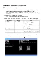

4T-B70CJ1 TROUBLE SHOOTING 4 - 27
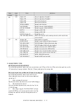
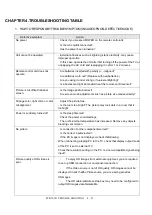
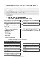
2. HOW TO RESPOND BY TROUBLE SYMPTOM (IN CASE OF DEFECTIVEMODE)
No
Description
1
No Power (front LED failure to light up) or no startup (front LED failure to turn red to green)
2
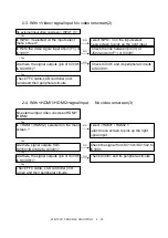
With [RF]signalinput No video onscreen(1)
3
With <Video>signalinput No video onscreen(2)
4
With <HDMI1/HDMI2>signalinput
No video onscreen(3)
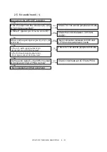
5
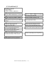
No audio heard (1)
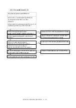
6
No audio heard (2)
7
No audio heard (3)
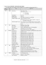
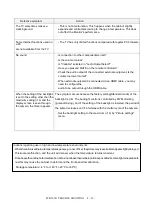
2-1. No Power (front LED failure to light up)
or no startup (front LED failure to turn red to green)
NO
↓
Yes
NO
↓
Yes
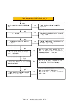
2-2. With [RF]signalinput No video onscreen(1)
↓
Yes
NO
↓
Yes
NO
↓
Yes
NO
↓
Yes
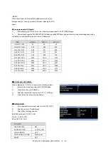
Are the DC/DC converter outputs and the output voltages
along the control lines as specified?
1) D5.1V_USB (IC9607)
2) D3.3V (IC9605)
3) D1.8V (IC9601)
4) CPU D1.0V (IC9604)
5) CORE D1.0V (IC9603)
6) D1.5V (IC9608)
7) BU+5V (IC9610)
8) BU+3.3V (IC9605)
9) BU1.0V (IC9609)
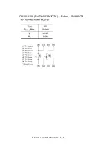
10) PNL+12V (60"/70":Q3804, 80":Q3801)
NO
Check the DC/DC converters and the
control lines. Replace defective parts as
required.
Check FFC cable, LCD controller (incl.
panel) and their peripheral circuits.
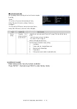
No video in the UHF/VHF reception
Are the wire harnesses and other cables properly
connected in the set?
Reconnect the wire harnesses and other cables
properly in the set.
Are the PS_ON and PANEL_EN signals both
about 3.3V?
PS_ON:Q9607(G), PNL_EN:Q3803(G)[60"/70"]
Q3802(G)[80"]
Check the PS_ON and PANEL_EN signal line.
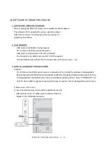
Is there IF output from the tuner
pin(6,7,8,9) of TU1102 as specified ?
Check TU1102 and its peripheral circuits.
Is there IF input at pin K1 & K2 of IC3301 ?
Check the circuit between TU1102 &
IC3301.
Are there the signal outputs (pin of IC3301
to SC 3801) ?
Check IC3301 and its peripheral circuit to
SC3801
Summary of Contents for Aquous 4T-B70CJ1U
Page 1: ...SHARP SERVICE MANUAL 4K ULTRA HD TV MODEL 4T B70CJ1U ...
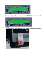
Page 8: ...6 2 Remove the 4 VESAscrews M6X12 3 Remove the 19 screws M3X8 at the rear cover area ...
Page 13: ...11 3 Remove 5 screws M3X6 in the main area Redcircle ...
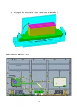
Page 18: ...16 2 Pull open the hook of IR Lens then take IR Board out WIRE DRESSING LAY OUT ...
Page 36: ...4T B70CJ1 TROUBLE SHOOTING 4 34 ...
Page 37: ...4T B70CJ1 TROUBLE SHOOTING 4 35 ...
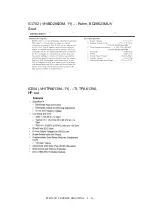
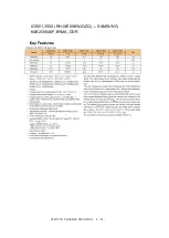
Page 40: ...4T B70CJ1 TROUBLE SHOOTING 4 38 IC3501 3502 RH IXE098WJQZQ SAMSUNG K4B2G1646F BYMA DDR ...
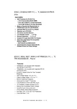
Page 41: ...4T B70CJ1 TROUBLE SHOOTING 4 39 IC3101 RH IXE112WJQZQ SAMSUMG KLM4G1FETE B041 eMMC ...
Page 42: ...4T B70CJ1 TROUBLE SHOOTING 4 40 IC8102 RH IXE211WJQZY DIALOG AS3824E1 ZQFT LED Drive ...
Page 43: ...4T B70CJ1 TROUBLE SHOOTING 4 41 ...
Page 44: ...4T B70CJ1 TROUBLE SHOOTING 4 42 Q8101 8108 RH TXA102WJQZY Rohm SH8KA4TB ...
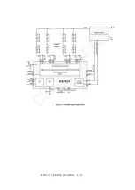
Page 45: ...4T B70CJ1 TROUBLE SHOOTING 4 43 CHAPTER 6 BLOCK DIAGRAM WIRING DIAGRAM 1 BLOCK DIAGRAM ...
Page 48: ...4T B70CJ1 TROUBLE SHOOTING 4 46 MAIN BOTTOM ...
Page 49: ...4T B70CJ1 TROUBLE SHOOTING 4 47 2 POWER UNIT PRINTED WIRING BOARD POWER TOP ...
Page 50: ...4T B70CJ1 TROUBLE SHOOTING 4 48 POWERBOTTOM ...
Page 52: ...4T B70CJ1 TROUBLE SHOOTING 4 50 CHAPTER 8 SCHEMATIC DIAGRAM 1 MAIN SCHEMATIC DIAGRAM ...
Page 53: ...4T B70CJ1 TROUBLE SHOOTING 4 51 ...
Page 54: ...4T B70CJ1 TROUBLE SHOOTING 4 52 ...
Page 56: ...4T B70CJ1 TROUBLE SHOOTING 4 54 4 KEY SCHEMATIC DIAGRAM ...
Page 59: ...4T B70CJ1 TROUBLE SHOOTING 4 57 2 CABINET PARTS ...
Page 60: ...4T B70CJ1 TROUBLE SHOOTING 4 58 3 SUPPLIED ACCESSORIES ...
Page 61: ...4T B70CJ1 TROUBLE SHOOTING 4 59 4 PACKING PARTS ...