LC-42/46/52D85X
5 – 18
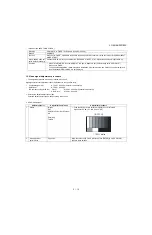
11. White Balance Adjustment
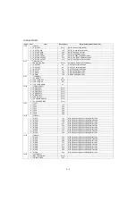
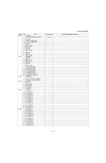
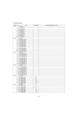
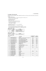
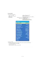
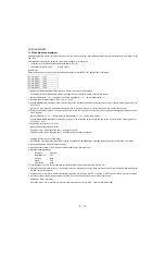
Adjustment gradation values (IN) appear on page 11/32 of process adjustment, and adjustment initial values (offset value) appear on pages 12/32
and 13/32.
For white balance adjustment, adjust the offset values on pages 12/32 and 13/32.
[Condition of the unit for inspection]: Modulated light: MAX (+16)
[Adjustment reference device] : Minolta CA-210
[Adjustment]
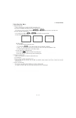
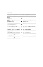
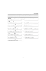
Check that the values on page 11/32 of process adjustment are set as below. If not, change them accordingly.
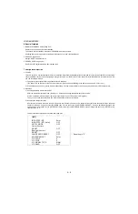
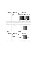
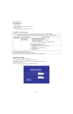
1) Display the current adjustment status at point 6. (Page 11/32 of process adjustment)
The display for checking the adjustment status is toggled by pressing the “6” button on the remote control.
(Normal OSD display
→
“6”
→
display for check (OSD disappears)
→
“6”
→
normal OSD display
→
. . . )
2) Read the value of the luminance meter. x=0.272, y =0.277
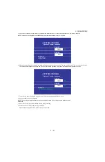
3) Change MG6R/MG6B (Adjustment offset value) on page 13/32 of process adjustment so that the values of the luminance meter approach x=0.272
and y =0.277.
(Basically, G is not changed. If adjustment fails with R and B, change G. When G is lowered, the weaker of R and B must be fixed.)
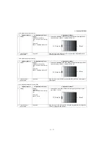
4) Display the adjustment status of the current point 5. (Each time the “5” button on the remote control is pressed, the adjustment status check dis-
play is toggled.)
(Normal OSD display
→
“5”
→
Check display (OSD disappears)
→
“5”
→
Normal OSD display
→
. . . )
Change MG5R/MG5B (adjustment offset value) on page 13/32 of process adjustment so that the values of the luminance meter approach x =
0.272 and y = 0.277.
5) Repeat step 4) for points 4, 3, 2, and 1.
[Adjustment reference standard value]
Adjustment spec
±
0.002 Inspection spec
±
0.004 (point 1 and 2)
Adjustment spec
±
0.001 Inspection spec
±
0.002 (Excluding the above-mentioned)
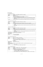
* Adjusting procedure by use of [RS-232C]
1. Get ready the PC with COM port (RS-232C) running on Windows 95/98/ME/2000/XP operating system, as well as the RS-232C cross cable.
2. Start the unit with the RS-232C cable connected.
3. Start the terminal software. (The freeware readily available on the Internet will do.)
4. Make the following settings.
5. If the settings are correct, the terminal software indicates “ERR” against pressing of the “ENTER” key.
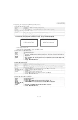
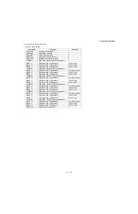
6. After the settings are done correctly, it is possible to make an adjustment by typing in the command shown in the table below and pressing the
“ENTER” key on the keyboard.
7. Command entry is successful if the terminal software indicates “OK” when the “ENTER” is pressed. If “ERR” is shown, retry to enter the command.
8. Send the process mode switching command to switch from the RS232C operation mode to the process mode.
KRSW0001: “ERR” is returned.
KKT10037: When “OK” is returned, the process mode becomes active. When “ERR”, start over from KRSW0001.
Point 1 (LEV1)
176
Point 2 (LEV2)
352
Point 3 (LEV3)
528
Point 4 (LEV4)
656
Point 5 (LEV5)
800
Point 6 (LEV6)
928
Baud rate
9,600 bps
Data LENGTH
8 bit
Parity bit
None
Stop bit
1 bit
Flow control
None

