5
LC-37HV4M
LC-37HV4H
OPERATION MANUAL
P
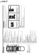
a
rt
names
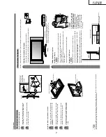
OPC indicator*
ST
ANDBY/ON indicator
(MAIN POWER)
button
OPC sensor
Displa
y
(ST
ANDBY/ON)
button
INPUT
button
buttons
( VOL
/
)
CHANNEL buttons
(CH
/
)
Remote contr
o
l sensor
*OPC: Optical Pictur
e Contr
o
l
CLEAR
*
(POWER) button
INPUT 4 ter
m
inal (S-VIDEO)
PC INPUT ter
m
inal (AUDIO)
INPUT 4 ter
m
inals (AUDIO)
PC INPUT ter
m
inal
(ANALOG RGB)
*
If the A
VC System is switched on but it does not appear to be operating corr
ectly
, it may need r
e
setting. In this
case, pr
ess
CLEAR
, shown in the diagram, lightly with the end of a ballpoint pen or other pointed object.
This will r
eset the System as shown below
.
•
A
V
MODE r
esets to USER.
•
TV channel r
esets to channel 1.
•
Dual scr
een r
esets to nor
mal.
•
Audio setting initialises.
•
SRS r
esets to OFF
.
•
Image position is initialised.
NO
TE
•
Pressing
CLEAR
will not work if the System is in standby mode (indicator lights r
ed).
•
Pressing
CLEAR
will not delete channel pr
eset or passwor
d. See page 60 for clearing the passwor
d when you know it.
See page for initialising to the factor
y pr
eset values when you forget your passwor
d.
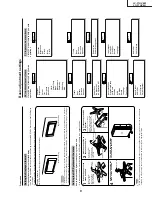
A
VC System
ST
ANDBY/ON indicator
INPUT 4 ter
m
inal (VIDEO)
(How to open the door)
Fr
ont vie
w
Rear vie
w
Headphone
(When connecting headphones,
the sound fr
om the speakers is
muted.)
ANTENNA INPUT
ter
m
inal
INPUT 3
ter
m
inal
(S-VIDEO)
INPUT 3
ter
m
inal
(VIDEO)
INPUT 3
COMPONENT
VIDEO ter
m
inals
(Y
, P
B
, P
R
)
INPUT 3 ter
m
inals
(AUDIO)
INPUT 1 ter
m
inal
(S-VIDEO)
INPUT 1 ter
m
inal
(VIDEO)
INPUT 1 COMPONENT
VIDEO ter
m
inals (Y
, P
B
, P
R
)
INPUT 1 ter
m
inals
(AUDIO)
RS-232C ter
m
inal
DISPLA
Y OUTPUT
-1
ter
m
inal
AC INPUT ter
m
inal
DISPLA
Y OUTPUT
-2
ter
m
inal
INPUT 2 ter
m
inals (AUDIO)
INPUT 2 ter
m
inal
(VIDEO)
INPUT 2 ter
m
inal (S-VIDEO)
MONITOR OUTPUT ter
minals (AUDIO)
MONITOR OUTPUT ter
minal (VIDEO)
MONITOR OUTPUT ter
minal
(S-VIDEO)
DC OUTPUT ter
minal (T
er
minal for
expanded functionality in the near futur
e.)
Summary of Contents for AQUOS LC-37HV4M
Page 26: ...26 8 7 10 9 6 5 4 3 2 1 A B C D E F G H LC 37HV4M LC 37HV4H CHASSIS LAYOUT ...
Page 27: ...27 17 16 19 18 15 14 13 12 11 10 LC 37HV4M LC 37HV4H ...
Page 33: ...33 6 5 4 3 2 1 A B C D E F G H LC 37HV4M LC 37HV4H Ë Ë Ë Ë Ë R C LED Unit Display ...
Page 34: ...34 8 7 10 9 6 5 4 3 2 1 A B C D E F G H LC 37HV4M LC 37HV4H Ë MAIN Unit 1 9 Display ...
Page 35: ...35 17 16 19 18 15 14 13 12 11 10 LC 37HV4M LC 37HV4H ...
Page 36: ...36 8 7 10 9 6 5 4 3 2 1 A B C D E F G H LC 37HV4M LC 37HV4H Ë MAIN Unit 2 9 Display ...
Page 37: ...37 17 16 19 18 15 14 13 12 11 10 LC 37HV4M LC 37HV4H ...
Page 38: ...38 8 7 10 9 6 5 4 3 2 1 A B C D E F G H LC 37HV4M LC 37HV4H Ë MAIN Unit 3 9 Display ...
Page 39: ...39 17 16 19 18 15 14 13 12 11 10 LC 37HV4M LC 37HV4H ...
Page 40: ...40 8 7 10 9 6 5 4 3 2 1 A B C D E F G H LC 37HV4M LC 37HV4H Ë MAIN Unit 4 9 Display ...
Page 41: ...41 17 16 19 18 15 14 13 12 11 10 LC 37HV4M LC 37HV4H ...
Page 42: ...42 8 7 10 9 6 5 4 3 2 1 A B C D E F G H LC 37HV4M LC 37HV4H Ë MAIN Unit 5 9 Display ...
Page 43: ...43 17 16 19 18 15 14 13 12 11 10 LC 37HV4M LC 37HV4H ...
Page 44: ...44 8 7 10 9 6 5 4 3 2 1 A B C D E F G H LC 37HV4M LC 37HV4H Ë MAIN Unit 6 9 Display ...
Page 45: ...45 17 16 19 18 15 14 13 12 11 10 LC 37HV4M LC 37HV4H ...
Page 46: ...46 8 7 10 9 6 5 4 3 2 1 A B C D E F G H LC 37HV4M LC 37HV4H Ë MAIN Unit 7 9 Display ...
Page 47: ...47 17 16 19 18 15 14 13 12 11 10 LC 37HV4M LC 37HV4H ...
Page 48: ...48 8 7 10 9 6 5 4 3 2 1 A B C D E F G H LC 37HV4M LC 37HV4H Ë MAIN Unit 8 9 Display ...
Page 49: ...49 17 16 19 18 15 14 13 12 11 10 LC 37HV4M LC 37HV4H ...
Page 50: ...50 8 7 10 9 6 5 4 3 2 1 A B C D E F G H LC 37HV4M LC 37HV4H Ë MAIN Unit 9 9 Display ...
Page 51: ...51 17 16 19 18 15 14 13 12 11 10 LC 37HV4M LC 37HV4H ...
Page 52: ...52 8 7 10 9 6 5 4 3 2 1 A B C D E F G H LC 37HV4M LC 37HV4H Ë Ë Ë Ë Ë AUDIO Unit 1 2 Display ...
Page 53: ...53 17 16 19 18 15 14 13 12 11 10 LC 37HV4M LC 37HV4H ...
Page 54: ...54 8 7 10 9 6 5 4 3 2 1 A B C D E F G H LC 37HV4M LC 37HV4H Ë Ë Ë Ë Ë AUDIO Unit 2 2 Display ...
Page 55: ...55 17 16 19 18 15 14 13 12 11 10 LC 37HV4M LC 37HV4H ...
Page 56: ...6 5 4 3 2 1 A B C D E F G H 56 LC 37HV4M LC 37HV4H Ë Ë Ë Ë Ë INVERTER 1 Unit Display ...
Page 57: ...57 6 5 4 3 2 1 A B C D E F G H LC 37HV4M LC 37HV4H Ë INVERTER 2 Unit Display ...
Page 58: ...6 5 4 3 2 1 A B C D E F G H 58 LC 37HV4M LC 37HV4H Ë Ë Ë Ë Ë INVERTER 3 Unit Display ...
Page 59: ...59 6 5 4 3 2 1 A B C D E F G H LC 37HV4M LC 37HV4H Ë INVERTER 4 Unit Display ...
Page 60: ...60 8 7 10 9 6 5 4 3 2 1 A B C D E F G H LC 37HV4M LC 37HV4H Ë Ë Ë Ë Ë Power Unit Display ...
Page 61: ...61 17 16 19 18 15 14 13 12 11 10 LC 37HV4M LC 37HV4H ...
Page 62: ...6 5 4 3 2 1 A B C D E F G H 62 LC 37HV4M LC 37HV4H Ë KEY Unit Display ...
Page 65: ...65 17 16 19 18 15 14 13 12 11 10 LC 37HV4M LC 37HV4H ...
Page 69: ...69 17 16 19 18 15 14 13 12 11 10 LC 37HV4M LC 37HV4H ...
Page 73: ...73 17 16 19 18 15 14 13 12 11 10 LC 37HV4M LC 37HV4H ...
Page 85: ...85 6 5 4 3 2 1 A B C D E F G H LC 37HV4M LC 37HV4H Ë Ë Ë Ë Ë Display POWER Unit Wiring Side ...

