5
LC-20S4E
OPERATION MANUAL
P
a
rt
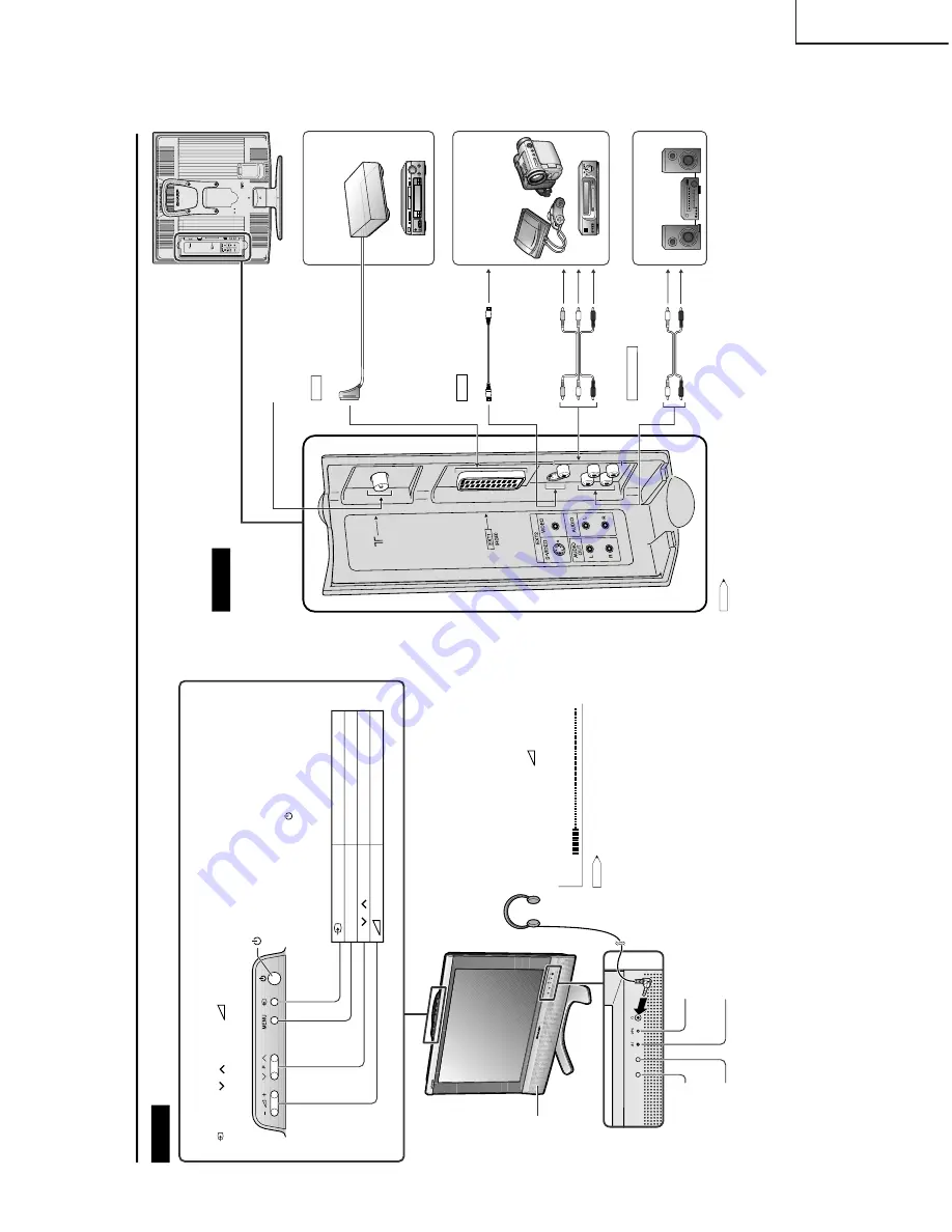
Names of the Main Unit
OPC sensor
Remote sensor
OPC
(Optical Picture Control) indicator
The OPC indicator lights up green when the "Backlight"
is set
to "Auto
(OPC)".
STANDBY/ON
indicator
The STANDBY/ON indicator lights up green when the power is on, and red when
in the standby mode (the indicator will not light when the main power is off).
Upper control panel
Ë
Using the control panel of the main unit
•
(Input)
,
P (
)/(
) (Channel)
,
(–)/(+) (Volume)
and
MENU
on the control panel of the main unit have the same functions
as the same buttons on the remote control. Fundamentally,
this operation manual provides a description based on operation using
the remote control.
Speaker
Headphones
Plug
the headphone mini-plug into the headphone jack.
Adjust the sound volume using
(+)/(–)
on the
remote control.
NOTE
•
Headphones are not included in the supplied accessories.
•
No sound is heard from the main unit speakers when a
headphone mini-plug is connected into the headphone jack.
•
Do not set the volume at a high level. Hearing experts
advise against extended listening at high volume levels.
Controls
(MAIN POWER)
•
The STANDBY/ON indicator instantly changes from red to green and the
LCD TV set is turned on.
•
To turn off the main power, press
again.
Ë
Operating the menu with the control panel
Button operations on the control panel correspond to the ones on the
remote control as shown below.
On-screen display
TV Volume
10
( Input
)
OK
on the remote control
MENU
MENU
on the remote control
P
(
)/
(
)(
Channel
)
"
/
'
on the remote control
(–)
/(+)
( Volume
)
\
/
|
on the remote control
<Example>
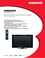
Decoder
VCR
DVD Player
To EXT1 terminal
To EXT2
terminal
21-pin Eur
o-SCAR
T connector
Antenna
terminal
<Example>
Audio amplifier
<Example>
DVD Player
VCR
Camcorder
Home video game system
To AUDIO OUT terminal
A
udio/Video cable
Video
A
u
dio (L)
A
u
dio (R)
A
u
dio (L)
A
u
dio (R)
S-Video cable
S-Video
A
udio cable
EXT1
EXT2
A
UDIO OUT
RGB (21-pin Eur
o-SCAR
T)
VIDEO
A
UDIO (L)
A
UDIO (R)
A
UDIO OUT (L)
A
UDIO OUT (R)
S-VIDEO
Connecting External De
vices
Terminals
You can enjoy picture and sound by connecting devices, such as a VCR or home video
game system, to the terminals located on the rear of the LCD TV set.
When connecting an external device, turn off the power of the LCD TV set first to prevent
any possible damage.
NOTE
•
For the cable, use a commercially available audio/video cable.
•
PC connection is not possible.
•
For more information about external device connections, see the operation manuals of your external devices.
•
Make sure that the corresponding cables are connected to each terminal. Connecting other cables may result in a malfunction.
•
EXT2 has two terminals, VIDEO and S-VIDEO terminals. If your external device has an S-VIDEO terminal, S-VIDEO connection is
recommended. S-VIDEO provides a finer, more detailed picture. If both terminals are connected, S-VIDEO terminal takes a priorit
y.
Summary of Contents for Aquos LC-20S4E
Page 29: ...31 6 5 4 3 2 1 A B C D E F G H LC 20S4E SCHEMATIC DIAGRAM Ë INVERTER Unit ...
Page 30: ...33 32 LC 20S4E 12 11 10 9 8 7 6 5 4 3 2 1 A B C D E F G H Ë SUB Unit 1 2 ...
Page 31: ...35 34 LC 20S4E 12 11 10 9 8 7 6 5 4 3 2 1 A B C D E F G H Ë SUB Unit 2 2 ...
Page 32: ...37 36 LC 20S4E 12 11 10 9 8 7 6 5 4 3 2 1 A B C D E F G H Ë MAIN Unit 1 4 ...
Page 33: ...39 38 LC 20S4E 12 11 10 9 8 7 6 5 4 3 2 1 A B C D E F G H Ë MAIN Unit 2 4 ...
Page 34: ...41 40 LC 20S4E 12 11 10 9 8 7 6 5 4 3 2 1 A B C D E F G H Ë MAIN Unit 3 4 ...
Page 35: ...43 42 LC 20S4E 12 11 10 9 8 7 6 5 4 3 2 1 A B C D E F G H Ë MAIN Unit 4 4 ...
Page 36: ...44 6 5 4 3 2 1 A B C D E F G H LC 20S4E Ë OPERATION Unit ...
Page 37: ...45 6 5 4 3 2 1 A B C D E F G H LC 20S4E Ë R C LED Unit ...


