8
LC-20E1U
LC-20E1UB/UW
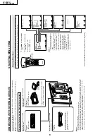
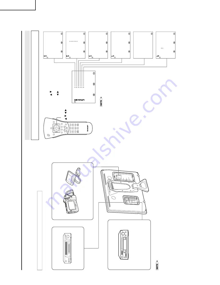
CONNECTING
WITH EXTERNAL
DEVICES
You can enjoy picture and sound by connecting a VCR or a home video game system to the terminals
located on the rear of the TV set.
When connecting an external device, turn off the power of the main unit first to prevent any possible
damage.
<Example>
•
Video camera
•
Home video game system
External devices that can be connected
to COMPONENT terminal
•
PC connection is not possible.
•
For the cable, use a commercially available audio/video cable.
•
Only connect audio/video signals to AV-IN1 and 2 terminals. Connecting other signals may result in a malfunction.
•
AV-IN1 has 2 video input terminals: VIDEO and S-VIDEO. When you connect external devices to both terminals
(and if you select AV-IN1), you can only view pictures from the S-VIDEO terminal. To view the picture from the
VIDEO terminal, do not connect any external device to the S-VIDEO terminal.
•
For more information about external device connections, see the manuals of your external devices.
A
V
-I
N
1
L
R
A
U
D
IO
S
-V
IDE
O
A
N
T.
V
ID
E
O
P
O
W
E
R
IN
P
U
T
D
C
1
3
V
HE
A
D
P
H
O
N
E
Y
P
B
C
O
M
P
O
N
E
N
T
P
R
L
L
R
A
V
-I
N
2
/O
U
T
V
ID
E
O
AU
DI
O
R
AU
DI
O
TUNER/B
A
ND
DV
D
A
UX 1
A
UX 3
A
UX 2
SURR
OUND
ON/OFF
TUNER/B
A
ND
DV
D
A
UX 1
A
UX 3
A
UX 2
SURR
OUND
ON/OFF
Example of external devices that can be connected
External devices that can be connected
to AV-IN2 terminal
*
If your external device has a component
terminal, COMPONENT connection is
recommended
(you can view high-quality
pictures).
<Example>
•
DVD, etc.
<Example>
•
VCR
•
Laser disc player
*
If your external device has an S-Video terminal,
S-VIDEO connection is recommended.
External devices that can be connected
to AV-IN1 terminal
M
EN
U
SL
E
EP
T
IM
ER
V
IDEO
A
D
JU
S
T
PR
E
S
E
T
C
LO
S
ED
CA
P
T
IO
N
V
–CH
IP
BLO
CK
SE
T U
P
SE
L
EC
T
:
EN
T
ER
:
EXIT
:
MENU
SL
E
EP
T
IM
ER
SE
L
EC
T
:
AD
JU
S
T
:
EX
IT
:
MENU
R
E
TURN
SL
E
EP
T
IM
ER
[
–
–
–
R
EM
AI
N
]
PI
C
TU
R
E
[
3
0
]
TI
N
T
CO
LO
R
BL
AC
K L
E
V
E
L
SHARP
N
E
S
S
SE
L
EC
T
:
EN
T
ER
:
EX
IT
:
MENU
V
IDEO
A
D
JU
S
T
(T
V
)
R
E
TURN
[
0
]
[
0
]
[
0
]
[
0
]
BR
IG
H
TNE
S
S
[B
R
IG
H
T
]
AU
TO
P
OW
ER
O
F
F
PIC
TU
R
E
F
LIP
A
V
2 IN/
O
U
T
SE
L
EC
T
:
EX
IT
:
MENU
R
E
TURN
[O
F
F ]
OR
M
AL
]
[I
N
]
PR
E
S
E
T
AD
JU
S
T
:
CC
/T
EX
T
[O
F
F
]
SE
L
EC
T
:
EXIT
:
MENU
R
E
TURN
AD
JU
S
T
:
C
LO
S
ED
CA
P
T
IO
N
IN
PUT
S
E
C
R
E
T
N
O
.
––––
EX
IT
:
MENU
BLU
E S
CRE
EN
[O
F
F
]
LA
NGU
AG
E
SE
L
EC
T
:
EXIT
:
MENU
R
E
TURN
AD
JU
S
T
:
SE
T U
P
CH
–S
E
T
T
IN
G
CO
LO
R S
Y
S
T
EM
R
ESE
T
[
N
3
5
8
]
SELECTING MENU ITEMS
•
This LCD
TV set allo
ws y
ou to adjust the
v
a
rious settings using the men
u screen.
Select the desired
menu item
b
y
f
ollo
wing the steps belo
w and then ref
er to the indicated page f
or details
.
1
Press
MENU
to display
the
MENU
screen.
2
Press
/
to select
the
desired
menu item.
3
Press
/
to enter.
4
Press
MENU
to exit.
•
The TINT display only appears when
the color system is set to N358 or
N443.
•
The displayed items differ depending
on the setting conditions.
•
The selected item changes to yellow.
•
Items in magenta cannot be se-
lected.
•
This product is factory set to comply
with the color system in the United
States (NTSC-N358). For Brazil
(PAL-M), Argentina (PAL-N) and
Uruguay (PAL-N), set the color
system before using this product.
•
To return to the previous screen,
select RETURN.
•
You can adjust some settings with
the special buttons: CC, PIC. FLIP,
SLEEP and BRIGHT
Selecting Menu Items
CH
VOL
P
O
W
E
R
MENU
DISPLAY
MUTE
SLEEP
PIC. FLIP
BRIGHT
CC
TV/VIDEO
FLASHBAC
K
* The
screen
indications
shown above
are
larger
than
actual
for
easy
reading.
MENU/
/
/
/
Summary of Contents for Aquos LC 20E1U
Page 32: ...35 34 LC 20E1U LC 20E1UB UW 12 11 10 9 8 7 6 5 4 3 2 1 A B C D E F G H OVERALL WIRING DIAGRAM ...
Page 35: ...39 38 LC 20E1U LC 20E1UB UW 12 11 10 9 8 7 6 5 4 3 2 1 A B C D E F G H Ë DIGITAL Unit 1 5 ...
Page 36: ...41 40 LC 20E1U LC 20E1UB UW 12 11 10 9 8 7 6 5 4 3 2 1 A B C D E F G H Ë DIGITAL Unit 2 5 ...
Page 37: ...43 42 LC 20E1U LC 20E1UB UW 12 11 10 9 8 7 6 5 4 3 2 1 A B C D E F G H Ë DIGITAL Unit 3 5 ...
Page 38: ...45 44 LC 20E1U LC 20E1UB UW 12 11 10 9 8 7 6 5 4 3 2 1 A B C D E F G H Ë DIGITAL Unit 4 5 ...
Page 39: ...47 46 LC 20E1U LC 20E1UB UW 12 11 10 9 8 7 6 5 4 3 2 1 A B C D E F G H Ë DIGITAL Unit 5 5 ...
Page 40: ...49 48 LC 20E1U LC 20E1UB UW 12 11 10 9 8 7 6 5 4 3 2 1 A B C D E F G H Ë ANALOG Unit 1 2 ...
Page 41: ...51 50 LC 20E1U LC 20E1UB UW 12 11 10 9 8 7 6 5 4 3 2 1 A B C D E F G H Ë ANALOG Unit 2 2 ...
Page 42: ...52 6 5 4 3 2 1 A B C D E F G H LC 20E1U LC 20E1UB UW Ë INVERTER A Unit ...
Page 43: ...53 6 5 4 3 2 1 A B C D E F G H LC 20E1U LC 20E1UB UW Ë INVERTER B Unit ...
Page 46: ...56 6 5 4 3 2 1 A B C D E F G H LC 20E1U LC 20E1UB UW DIGITAL Unit Side B ...
Page 49: ...59 6 5 4 3 2 1 A B C D E F G H LC 20E1U LC 20E1UB UW ANALOG Unit Side A ...
Page 51: ...62 6 5 4 3 2 1 A B C D E F G H LC 20E1U LC 20E1UB UW INVERTER A Unit Side A ...
Page 53: ...64 6 5 4 3 2 1 A B C D E F G H LC 20E1U LC 20E1UB UW INVERTER B Unit Side A ...


