


17
LC-20E1U
LC-20E1UB/UW
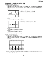
Test patterns in adjustment process mode
[1] IC801 (Video decoder) test patterns
1-1. Getting the test patterns displayed
Put the screen in AV1, AV2 or COMPONENT but keep out any signal. Call the adjustment process mode,
select “TEST PATTERN” in the 3rd line of page 8, make the settings 1 thru 6, and the following test patterns
show up.
1-2. Test patterns
»
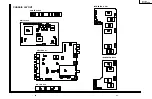
Setting 1
»
Setting 2
Finer vertical stripes than Setting 1 are displayed.
»
Setting 3
»
Setting 4
A rather dark green-only pattern is displayed.
»
Setting 5
A half-tone green-only pattern is displayed.
»
Setting 6
A rather bright green-only pattern is displayed.
[2] IC1201 (LCD controller) test pattern
2-1. Getting the test pattern displayed
Put the screen in AV1, AV2 or COMPONENT but keep out any signal. Call the adjustment process mode,
select “G/A TEST PATTERN” in the 13th line of page 17, turn on the setting, and the following test pattern
shows up.
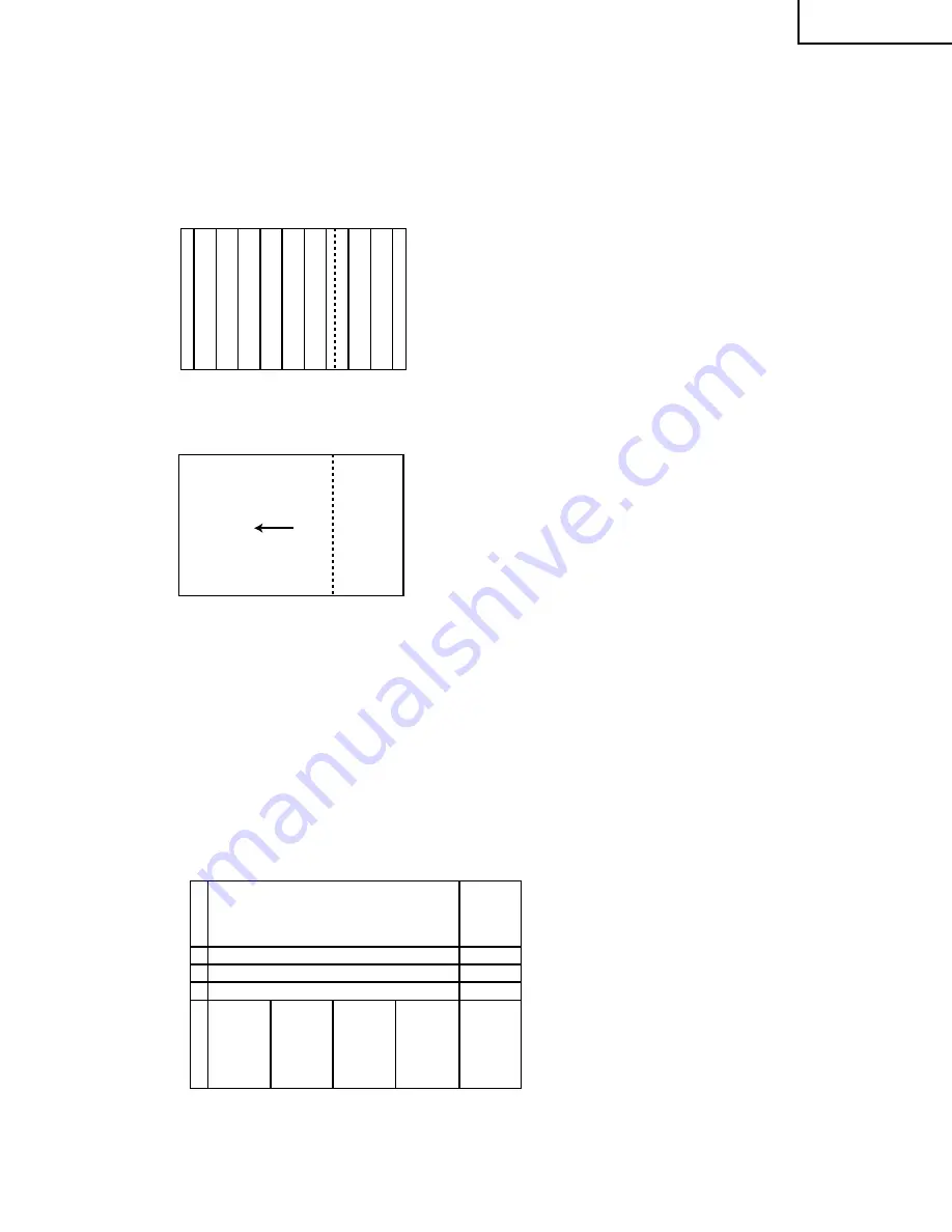
2-2. Test pattern
The following test pattern appears.
Note: When the IC801 and IC1201 test pattern display commands are both turned on at the same time, the IC1201
test pattern is given priority.
The color bars are displayed as shown at left.
The green pattern is displayed as shown at left.
g
reen
g
reen
Y
ello
w
Y
ello
w
Cy
an
Cy
an
Magenta
Magenta
Green
Green
Red
Blue
Bright
Bright
Dark
Green
Bright
Bright
Bright
Bright
Dark
Dark
Dark
Dark
Dark
Dark
Dark
Dark
Green
Red
Blue
Black
0-level
gradation
White
63-level
gradation
W
h
i
t
e
Gray
16-level
gradation
Gray
32-level
gradation
Gray
48-level
gradation
Gray scale
Summary of Contents for Aquos LC 20E1U
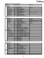
Page 32: ...35 34 LC 20E1U LC 20E1UB UW 12 11 10 9 8 7 6 5 4 3 2 1 A B C D E F G H OVERALL WIRING DIAGRAM ...
Page 35: ...39 38 LC 20E1U LC 20E1UB UW 12 11 10 9 8 7 6 5 4 3 2 1 A B C D E F G H Ë DIGITAL Unit 1 5 ...
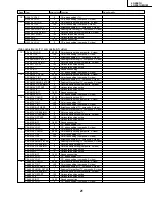
Page 36: ...41 40 LC 20E1U LC 20E1UB UW 12 11 10 9 8 7 6 5 4 3 2 1 A B C D E F G H Ë DIGITAL Unit 2 5 ...
Page 37: ...43 42 LC 20E1U LC 20E1UB UW 12 11 10 9 8 7 6 5 4 3 2 1 A B C D E F G H Ë DIGITAL Unit 3 5 ...
Page 38: ...45 44 LC 20E1U LC 20E1UB UW 12 11 10 9 8 7 6 5 4 3 2 1 A B C D E F G H Ë DIGITAL Unit 4 5 ...
Page 39: ...47 46 LC 20E1U LC 20E1UB UW 12 11 10 9 8 7 6 5 4 3 2 1 A B C D E F G H Ë DIGITAL Unit 5 5 ...
Page 40: ...49 48 LC 20E1U LC 20E1UB UW 12 11 10 9 8 7 6 5 4 3 2 1 A B C D E F G H Ë ANALOG Unit 1 2 ...
Page 41: ...51 50 LC 20E1U LC 20E1UB UW 12 11 10 9 8 7 6 5 4 3 2 1 A B C D E F G H Ë ANALOG Unit 2 2 ...
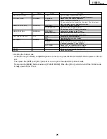
Page 42: ...52 6 5 4 3 2 1 A B C D E F G H LC 20E1U LC 20E1UB UW Ë INVERTER A Unit ...
Page 43: ...53 6 5 4 3 2 1 A B C D E F G H LC 20E1U LC 20E1UB UW Ë INVERTER B Unit ...
Page 46: ...56 6 5 4 3 2 1 A B C D E F G H LC 20E1U LC 20E1UB UW DIGITAL Unit Side B ...
Page 49: ...59 6 5 4 3 2 1 A B C D E F G H LC 20E1U LC 20E1UB UW ANALOG Unit Side A ...
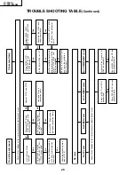
Page 51: ...62 6 5 4 3 2 1 A B C D E F G H LC 20E1U LC 20E1UB UW INVERTER A Unit Side A ...
Page 53: ...64 6 5 4 3 2 1 A B C D E F G H LC 20E1U LC 20E1UB UW INVERTER B Unit Side A ...


