background image

11

TV/
VIDEO

CH

MENU

E

TV/VIDEO

REVEAL

HOLD

END

M

MENU

SOUND

SUBTIT

LE

SUBPAGE

TEXT

ROTATE

WIDE

T

CH

VOL

MENU

SLEEP

DIS.MODE

OK

MPX

SUBTITLE

END

HOLD

SUBPAGE

REVEAL

TEXT

BRIGHT

TV/ VIDEO

POWER

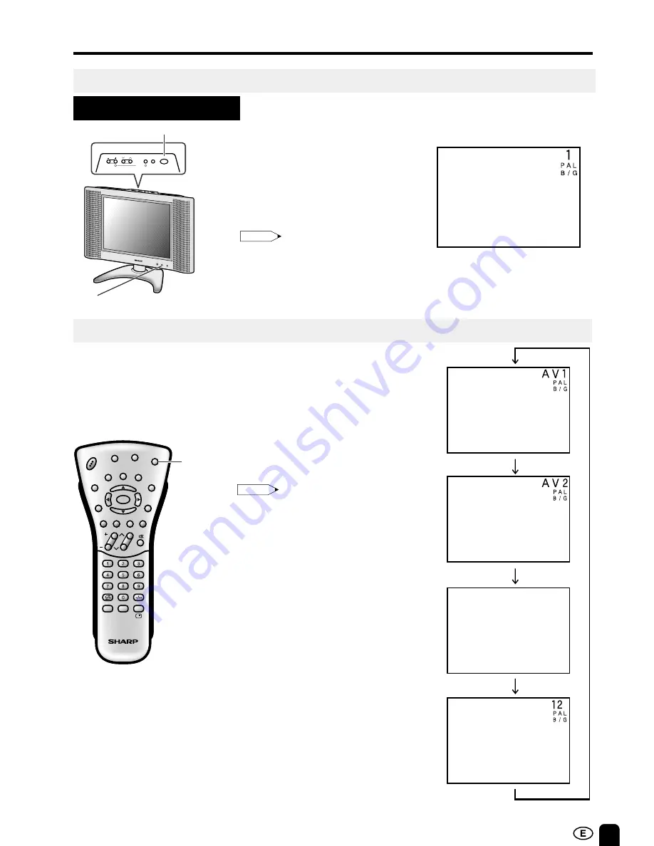
BASIC OPERATION

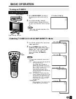
Control section of main unit

1

Press 

MAIN POWER

, located on

the upper part of the main unit to
ON.

2

The Power/Standby indicator
instantaneously changes from red
to green and the main unit is turned
on.

▼ 

On-Screen Display

Turning on POWER

Switching TV/VIDEO AV1/AV2/COMPONENT/TV Mode

Note:

Input mode indication disappears after
several seconds.

AV1 mode

AV2 mode

1

Turn on the power of the connected
video equipment.

2

Press 

TV/VIDEO

 and select the

applicable input source. The screen
displays AV1, AV2, COMPONENT
or TV mode at the upper right
corner each time 

TV/VIDEO

 is

pressed.

AV input mode indication remains for 5
seconds.

• AV1: Video equipment connected to the

AV1 input terminals.
An S-video input terminal is
additionally provided for the AV1
input. If both S-video terminal and
normal video terminals are
connected with cables, the S-
video input terminal is selected as
the high priority.

• AV2: AV2 mode is used to adjust the

preset settings and IN or OUT can
be selected. AV2 indication is not
displayed when OUT is selected.
(For details on setting AV-OUT,
see page 22.)

• COMPONENT:

Video equipment connected to the
COMPONENT input terminals.

Note:

COMPONENT      mode

C O M P O N E N T

TV mode

Power/Standby indicator

MAIN POWER

CH

MENU TV/VIDEO

MAIN POWER

VOL

PRESET 1

2

POWER

SLEEP

Summary of Contents for Aquos LC-13B4M

Page 1: ...ENGLISH LC 13B4M LC 15B4M LC 20B4M LCD COLOUR TELEVISION OPERATION MANUAL Printed in Japan TINS A742WJZZ 03P05 JKM Printed on post consumer recycled paper POWER SLEEP LC 13B4M LC 15B4M LC 20B4M ...
Page 2: ...2 ON OFF Standby 12 Changing the Channels 13 SELECTING THE MENU ITEMS 14 Selecting a Menu Item 14 Page PRESET 15 16 17 On Screen Display Language Selection 15 Presetting the Channels AUTO 15 Presetting the Channels MANUAL 16 Channel Setting 17 ADJUSTMENT 18 19 20 21 22 23 24 Adjusting the SLEEP TIMER Setting 18 Adjusting the PICTURE Settings 19 20 Adjusting the FEATURE Settings 21 22 Adjusting the...

Page 3: ...t provides stable voltage with minimum fluctuations Unstable power supply can cause problems in the product Overloading Do not overload AC outlets or extension cords Overloading can cause fire or electric shock Entering of objects and liquids Never insert an object into the product through vents or openings High voltage flows in the product and inserting an object can cause electric shock and or s...

Page 4: ...proper ventilation is provided or the manufacturer s instructions are followed When relocating the product placed on a cart it must be moved with utmost care Sudden stops excessive force and uneven floor surface can cause the product to fall from the cart Stand Do not place the product on an unstable cart stand tripod or table Placing the product on an unstable base can cause the product to fall r...

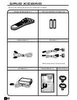
Page 5: ...M SUM 4 Dry Battery 2 AC Adapter 1 UBATU0026GEZZ UADP 0212CEZZ Cable Clamp 2 Operation Manual 1 Wireless Remote Control 1 ENGLISH LCD COLOUR TELEVISION OPERATION MANUAL Printed in Japan TINS A742WJZZ 03P05 JKM Printed on post consumer recycled paper POWER SLEEP LC 13B4M LC 15B4M LC 20B4M Product shape varies in some countries ...

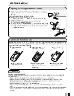
Page 6: ...he remote control is not used for an extended period of time remove batteries from the remote control Preparing and Using the Remote Control Use the remote control by pointing it towards the remote sensor window Objects between the remote control and sensor window may prevent proper operation Cautions regarding use of remote control Do not expose the remote control to shock In addition do not expo...

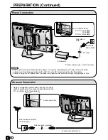
Page 7: ...uct and power outlet when not using for long periods of time PREPARATION Continued AC adapter AC cord Plug into AC outlet Household power outlet DC input terminal To antenna input terminal Antenna cable supplied DC 12V LC 13B4M LC 15B4M DC 13V LC 20B4M Antenna terminal Using the supplied antenna cable connect the room antenna terminal to the antenna input terminal on the TV set Refer to the figure...

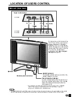
Page 8: ... TV VIDEO CH and VOL on the main unit have the same functions as the same buttons on the remote control Fundamentally this operation manual provides a description based on operation with the remote control Main unit front view The examples used throughout this manual are based on the LC 20B4M model There may be a slight difference in the illustrations if you are using the LC 13B4M and LC 15B4M mod...

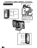
Page 9: ...ER INPUT DC 12V LC 13B4M LC 15B4M DC 13V LC 20B4M VIDEO AUDIO L Y PB PR R AUDIO L R COMPONENT AV IN2 OUT Y VIDEO AV IN2 OUT COMPONENT AUDIO L AUDIO R PB PR AUDIO L AUDIO R Carrying handle POWER INPUT DC13V USE THE SUPPLIED AC ADAPTER PART NO LOCATED ON THE MODEL LABEL How to adjust the angle Tilt the display by grabbing onto the carrying handle while securely holding down the stand with your other...

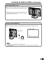
Page 10: ...nd press on the upper part of the back cover until the tab locks in place with a click Removing the Back Cover Plug the headphone mini plug into the HEADPHONE jack located on the rear of the TV set Headphones Note Headphones are not included in the supplied accessories No sound will be heard from the main unit speakers when a headphone mini plug is connected into the HEADPHONE jack On screen displ...

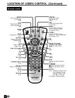
Page 11: ... REVEAL Displays hidden information such as solutions to riddles and puzzles P 29 Right Left Selection P 14 SUBPAGE Displays the Teletext Subpage directly P 28 TV VIDEO Switches the input source between AV1 AV2 COMPONENT and TV mode P 11 BRIGHT Selects the brightness of the display P 23 Green P 28 CH MENU E TV VIDEO REVEAL HOLD END M MENU SOUND SUBTITLE SUBPAGE TEXT ROTATE WIDE T CH VOL MENU SLEEP...

Page 12: ...DEO and select the applicable input source The screen displays AV1 AV2 COMPONENT or TV mode at the upper right corner each time TV VIDEO is pressed AV input mode indication remains for 5 seconds AV1 Video equipment connected to the AV1 input terminals An S video input terminal is additionally provided for the AV1 input If both S video terminal and normal video terminals are connected with cables t...

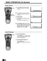
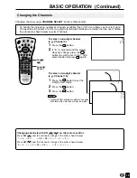
Page 13: ...Press MUTE to temporarily turn off the sound Screen displays the MUTE mark 2 Press MUTE or VOL to turn the sound back to the previous level MUTE is automatically cleared when the following buttons are pressed POWER VOL MUTE To turn off the LCD TV Press POWER on the remote control The Power Standby indicator will turn red Standby position To turn the LCD TV back on Press POWER again The Power Stand...

Page 14: ...used Follow the procedure shown below to select channels 1 Press the button to set the 2 digit select mode 2 Press the button 3 Press the button Note Complete this procedure within 4 seconds otherwise the selection will not be made To select a two digit channel e g Channel 15 Changing channels with CH on the remote control Press CH and the channels change in the order shown below 1 2 3 98 99 0 1 2...

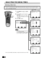
Page 15: ...oves up or down The mark indicates the selected menu item 3 Press to enter The displayed items differ depending on the setting conditions The selected item changes to yellow Items in purple cannot be selected AV mode Page 19 Selecting a Menu Item Note The screen indications shown above are larger than actual for easy reading MENU SELECT ADJUST EXIT CH SETTING RETURN POSITION CH15 COLOUR SYSTEM AUT...

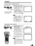
Page 16: ...odels Note When starting PRESET after setting the SOUND SYSTEM with MENU of the Remote Control the SOUND SYSTEM for all channels are stored into memory Unused channels are automatically skipped The Preset mode is only available in the TV mode and cannot be operated in the AV mode Sound System Presetting the Channels AUTO Automatically tunes in and presets receivable TV stations Make sure the anten...

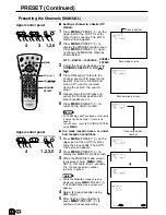
Page 17: ...rrectly if noise can be heard or if there is no sound In such case reset to SOUND SYSTEM using MENU PRESET Continued AUTO MANUAL LANGUAGE NORMAL SCREEN Setting a channel to a desired TV station Presetting the Channels MANUAL Upper control panel 1 2 6 3 VOL CH MENU TV VIDEO 1 2 PRESET 4 Sound System Auto mode screen Manual mode screen Channel position number In a weak reception area or under bad re...

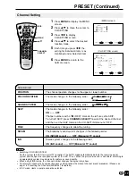
Page 18: ...the channel to its original frequency setting follow the manual channel preset procedure Please see page 16 Presetting the Channels MANUAL for details In AV mode items in purple cannot be selected MENU screen CH SETTING screen MENU MENU SLEEP TIMER PICTURE FEATURE CH SETTING SELECT ENTER EXIT MENU SELECT ADJUST EXIT CH SETTING RETURN POSITION CH15 COLOUR SYSTEM AUTO SOUND SYSTEM B G SKIP OFF FINE ...

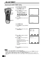
Page 19: ...ess MENU to return to the main screen 6 REMAIN 0 MENU MENU SLEEP TIMER PICTURE FEATURE CH SETTING SELECT ENTER EXIT SLEEP TIMER RETURN SLEEP TIMER 120 REMAIN MENU SELECT ADJUST EXIT 0 CH MENU E TV VIDEO REVEAL HOLD END M MENU SOUND SUBTITLE SUBPAGE TEXT ROTATE WIDE T CH VOL MENU SLEEP DIS MODE OK MPX SUBTITLE END HOLD SUBPAGE REVEAL TEXT BRIGHT TV VIDEO POWER MENU SLEEP POWER REMAIN Note When you ...

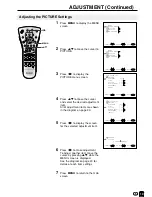
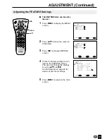
Page 20: ...ge 20 5 Press to display the screen for the selected adjustment item 6 Press to make adjustment To adjust another item move the cursor by pressing while the MENU screen is displayed See the diagram on page 20 for details of each item settings 7 Press MENU to return to the main screen RETURN COLOUR MENU SELECT ADJUST EXIT 0 MENU MENU SLEEP TIMER PICTURE FEATURE CH SETTING SELECT ENTER EXIT MENU MEN...

Page 21: ...o select COLOUR SYSTEM AV1 AV2 AUTO PAL SECAM N358 N443 PAL60 COMPONENT AUTO PAL NTSC Note COLOUR SYSTEM is displayed only in the AV mode Switching the COLOUR SYSTEM Set the system to AUTO for normal reception The AUTO mode automatically detects the receiving signal system and changes the reception system of the set When the picture or sound is not stable switching to an appropriate system may imp...

Page 22: ...age 22 for details of each item settings 5 Press MENU to return to the main screen MENU MENU SLEEP TIMER PICTURE FEATURE CH SETTING SELECT ENTER EXIT MENU MENU SLEEP TIMER PICTURE FEATURE CH SETTING SELECT ENTER EXIT CH MENU E TV VIDEO REVEAL HOLD END M MENU SOUND SUBTITLE SUBPAGE TEXT ROTATE WIDE T CH VOL MENU SLEEP DIS MODE OK MPX SUBTITLE END HOLD SUBPAGE REVEAL TEXT BRIGHT TV VIDEO POWER MENU ...

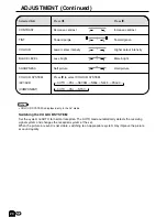
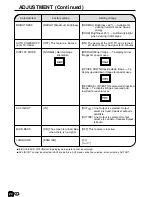
Page 23: ...nge NORMAL Brightness 60 Suitable for viewing in well lit areas Saves energy DARK Brightness 20 Sufficiently bright when viewing in dim areas ON The power of the LCD TV set is turned off when there is no signal for 5 minutes MIRROR Mirror image To display mirror images for special uses UPSIDE DOWN Upside down image To display upside down images for special uses REVERSE INVERT Reversed and inverted...

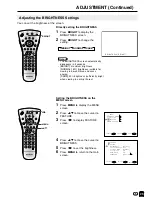
Page 24: ...ange the setting Setting the BRIGHTNESS on the MENU screen 1 Press MENU to display the MENU screen 2 Press to move the cursor to FEATURE 3 Press to display FEATURE screen 4 Press to move the cursor to BRIGHTNESS 5 Press to set the brightness 6 Press MENU to return to the main screen BRIGHT NORMAL DARK Note The BRIGHTNESS screen automatically disappears in 3 seconds BRIGHT maximum brightness NORMAL...

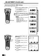
Page 25: ...IDE DOWN upside down image REVERSE INVERT reversed and inverted image CH MENU E TV VIDEO REVEAL HOLD END M MENU SOUND SUBTITLE SUBPAGE TEXT ROTATE WIDE T CH VOL MENU SLEEP DIS MODE OK MPX SUBTITLE END HOLD SUBPAGE REVEAL TEXT BRIGHT TV VIDEO POWER DIS MODE CH MENU E TV VIDEO REVEAL HOLD END M MENU SOUND SUBTITLE SUBPAGE TEXT ROTATE WIDE T CH VOL MENU SLEEP DIS MODE OK MPX SUBTITLE END HOLD SUBPAGE...

Page 26: ...tion set the OFF position of the NICAM to change the TV sound to monaural 1 Press MENU to display the MENU screen 2 Press to select CH SETTING 3 Press to display the CH SETTING menu 4 Press to select NICAM 5 Press to select OFF When the NICAM sound is set to the OFF position the TV sound is output in monaural 49 NICAM STEREO 49 MONO When stereo sound is received 49 NICAM M1 49 NICAM M2 49 MONO 49 ...

Page 27: ... TV sound to monaural 1 Press MENU to display the MENU screen 2 Press to select CH SETTING 3 Press to display the CH SETTING menu 4 Press to select IGR 5 Press to select OFF When the IGR sound is set to the OFF position the TV sound is output in monaural 49 49 MONO When stereo sound is received 49 MAIN 49 SUB When main sound is received STEREO When sub sound is received When off position is select...

Page 28: ... with the remote control and indirectly through the on screen display menu system Operating instructions in Teletext mode The FLOF system for teletext is transmitted in Singapore currently The TOP system for teletext is transmitted in Australia currently If TOP Teletext is broadcast a control line and TOP line can be displayed on the screen The TOP line involves the operating instructions associat...

Page 29: ... Teletext screen Press Red to display the previous page and Green to display the next page Yellow and Cyan are as indicated on the TOP line Note By using the Red button the previously selected page will appear down to the first page which showed up directly after switching on the video text Therefore the Red button has no function directly after switching on the video text 3 Changing subpages If a...

Page 30: ...set 1 Press MENU to display the CHARACTER SET screen 2 Press to select the desired character set The colour of the letters will turn to yellow When selecting the character set pressing will change the letters to magenta for an instant and then return them back to yellow 3 Press MENU to exit 6 Useful Features for Teletext The HOLD on the remote control can be used to hold the current teletext page ...

Page 31: ... IN1 you can only view pictures from the S VIDEO terminal To view the picture from the VIDEO terminal do not connect any external devices to the S VIDEO terminal For more information about external device connections see the manuals of your external devices Example Camcorder Home video game system External devices that can be connected to COMPONENT terminal Example of external devices that can be ...

Page 32: ... and audio cables to the corresponding terminals When a monaural audio source is connected to only one of the AUDIO input terminals sound will be heard not from both speakers but from only one speaker VIDEO AUDIO L Y PB PR R AUDIO L R COMPONENT AV IN2 OUT ANT VIDEO S VIDEO AUDIO L R HEAD PHONE AV IN1 To AV IN2 OUT terminal To AV IN1 terminal To S VIDEO input terminal S video Audio R Audio L Video ...

Page 33: ...nection to external audio systems Note You can output video and audio data from the TV set through the AV output terminals AV OUT When using as an OUTPUT terminal select FEATURE in the MENU and set AV2 IN OUT to OUT See page 21 The factory setting for AV2 IN OUT is IN Connect to a VCR audio amplifier etc How to Fix the Cables Fix cables and cords with the attached cable clamps so that they do not ...

Page 34: ...minal is free of connections There is no sound Make sure the volume is not set to minimum Make sure the sound is not set to mute There is no picture or sound just noise Make sure the antenna cable is properly connected Bad reception can be considered Picture is not clear Make sure the antenna cable is properly connected Bad reception can be considered Picture is light or improperly tinted Check co...

Page 35: ...apart There are stripes on the screen or colours fade Is the unit receiving interference from other devices Transmission antennas of radio broadcasting stations or amateur radios and cellular phones may also cause interference Use the unit as far apart as possible from devices that may cause possible interference Cautions regarding use in high and low temperature environments When the unit is used...

Page 36: ...mponent Headphone jack OSD LANGUAGE Power requirement Weight Accessories ITEMS MODEL LC 13B4M LC 15B4M LC 20B4M 13 33 cm Advanced Super View BLACK TFT LCD 921 600 dots VGA World multi system I DK M BG Auto preset tuning NICAM BG I DK IGR BG Yes Yes S1 S41 ch Hyper Band Yes 430 cd m2 60 000 Hours H 170 V 170 2 1W 2 4 7 cm Oval 2 pcs Composite Video S Video Audio Composite Video Audio Y PB PR Audio ...

Page 37: ...8 267 429 292 6 271 5 133 5 137 5 187 8 333 3 61 5 100 100 33 PRESET 1 2 L AUDIO VIDEO R AV IN 2 OUT Y PB PR COMPONENT L AUDIO R AV IN1 VIDEO S VIDEO HEAD PHONE ANT L AUDIO R MAINPOWER POWER SLEEP POWER INPUT DC12V USE THE SUPPLIED AC ADAPTER PART NO LOCATED ON THE MODEL LABEL VOL ...

Page 38: ...8 7 231 307 484 322 2 303 149 5 100 100 38 2 63 2 149 5 198 366 2 PRESET 1 2 L AUDIO VIDEO R AV IN 2 OUT Y PB PR COMPONENT L AUDIO R AV IN1 VIDEO S VIDEO HEAD PHONE ANT POWER INPUT DC12V L AUDIO R MAINPOWER POWER SLEEP USE THE SUPPLIED AC ADAPTER PART NO LOCATED ON THE MODEL LABEL VOL ...

Page 39: ... AV IN1 L AV IN 2 OUT COMPONENT R AUDIO VIDEO L R AUDIO L PR PB Y CH VOL TV VIDEO MENU MAINPOWER PRESET 1 2 POWER INPUT DC13V USE THE SUPPLIED AC ADAPTER PART NO LOCATED ON THE MODEL LABEL 68 6 471 5 300 8 381 5 193 5 188 76 1 420 630 470 3 110 7 249 6 76 1 403 3 100 51 5 100 POWER SLEEP ...

Page 40: ...LC 13B4H LC 15B4H LC 20B4H SHARP CORPORATION ...

Reviews: