


3) Insert the installation CD-ROM into a CD-ROM drive.
4) Choose File from the Menu bar in Program Manager, and
then choose the Run... command.
5) Type R:\SETUP (if the CD-ROM is designated as drive R)
in the command line box and then click the OK button.
6) Select a directory to which the printer driver will be in-
stalled and click the Next button. To install it to the default
directory, click the Next button.
7) A “printer port to be used” window will be displayed. Nor-
mally, LPT1 is automatically set.
Then ensure that Yes is checked to use this printer as the
default printer.
8) A “Confirm installation” window will be displayed. To con-
tinue installation, click Yes.
9) When the installation is complete, restart Windows.
4. AL-1000 Series printer driver group
When the printer driver is installed, the SHARP AL-1000 Series
printer driver group will be created. This group allows the fol-
lowing functions to be executed.
Uninstall AL-1000 Series
The printer driver can be uninstalled. If the driver is
uninstalled, printing cannot be performed on the printer.
For proper uninstallation, be sure to use uninstallation pro-
gram of the printer driver group.
Readme
The latest information on the printer driver is included in
this note. Read the Readme first.
Advanced Settings
See help for application support and application problems
that may occur when printing. See help for the applicable
method of usage.
Status Monitor
The printer state and information on current printing are
displayed on the status monitor window.
DOS Emulation Setup
Status Monitor HELP
DOS Emulation HELP
Advanced Settings HELP
●
Be sure to read “Readme” found in the printer driver group
before starting to print from application programs.
[5]
PARALLEL INTERFACE
This printer uses a bi-directional parallel interface. Use the sup-
plied interface cable.
Connector
36-pin DDK 57LE-40360-730B (D29) female connector or
equivalent connector
Cable
Shielded type bi-directional parallel interface
For best results,, use a printer interface cable which is
IEEE1284 compliant.
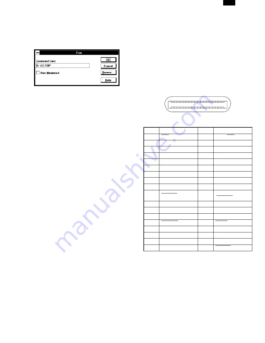
Pin configuration
The pin numbers and signal names are listed in the follow-
ing table.
Pin No.
Signal name
Pin No.
Signal name
1
STB
19
GND (STB RET)
2
DATA1
20
GND (DATA1 RET)
3
DATA2
21
GND (DATA2 RET)
4
DATA3
22
GND (DATA3 RET)
5
DATA4
23
GND (DATA4 RET)
6
DATA5
24
GND (DATA5 RET)
7
DATA6
25
GND (DATA6 RET)
8
DATA7
26
GND (DATA7 RET)
9
DATA8
27
GND (DATA8 RET)
10
ACKNLG
28
GND
(ACKNLG RET)
11
BUSY
29
GND (BUSY RET)
12
PE (Paper End)
30
GND (PE RET)
13
SLTC
31
INPRM
14
AUTO LF
32
FAULT
15
(NC)
33
(NC)
16
GND (0 V)
34
(NC)
17
FG
35
+5 V
18
+5 V
36
SLTC IN
1
18
36
19
AL-1041
4-3


