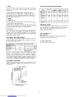
[2] TEST MODE
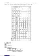
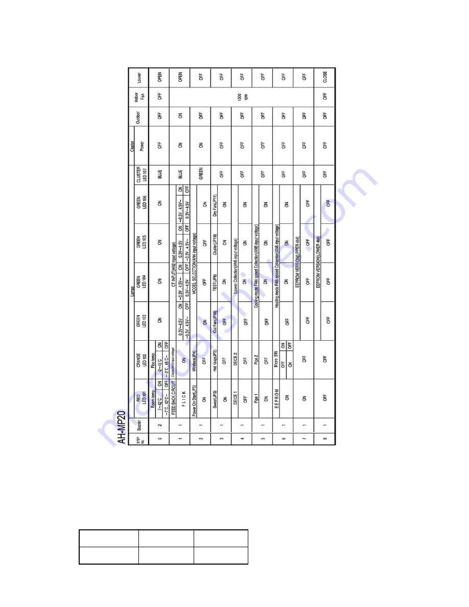
Keep pushing the "AUX." buttons and supply the power, the system will go to the test mode. In this mode, the output of operation is switched by
pushing the ""AUX." button in the unit or the "OI" button in the remote controller. Normal outputs are shown in Table.
2.1
PLASMA CLUSTER
Plasma cluster ion mode
SSR2 : ON
Relay (Cluster unit inside) : OFF
Minus ion mode
SSR2 : ON
Relay (Cluster unit inside) : ON
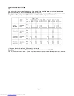
1) Cluster generator checking (STEP 1)
Time LED
ON
OFF
(Yellow)
Judgement
Normal
Failure
(Generator OK)
(Check circuit)
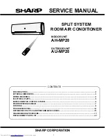
Summary of Contents for AH-MP20
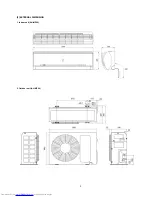
Page 3: ... 2 EXTERNAL DIMENSION 3 1 Indoor unit AH MP20 2 Outdoor unit AU MP20 ...
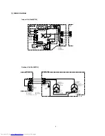
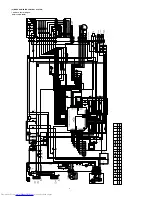
Page 4: ...4 Indoor Unit AH MP20 Outdoor Unit AU MP20 3 WIRING DIAGRAM CC097 UNIT TO UNIT CORD ...
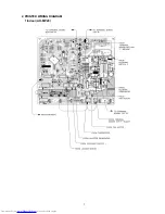
Page 7: ...2 PRINTED WIRING DIAGRAM 1 Indoor AH MP20 7 ...
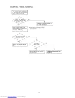
Page 12: ...CHAPTER 4 TROUBLESHOOTING 12 ...
Page 13: ...13 ...
Page 14: ......
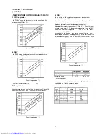
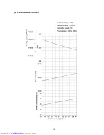
Page 16: ...1 14 16 2 PERFORMANCE CURVES ...

