E-5
INSTALLATION INSTRUCTIONS
6
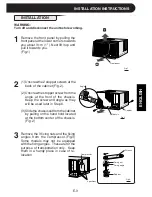
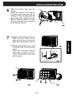
Slide the chassis back into the
cabinet.
Secure the chassis to the cabinet
using the screw and angle removed
in Step 2. Push the angle into the
gap between the chassis and the
cabinet. Slide the angle to the right
until the holes meet, and screw it on
to the chassis. (Fig.8)
Fig.8
Louver link
Crank shaft
Front panel back view
Fig.9
Fig.10
Grille
Fig.12
Front panel
Replace the front panel. (Fig.9)
Slide the crank shaft into the
opening of the louver link at the
back of the front panel. (Fig.10)
Remove the grille (Fig.11) and
the air filter (Fig.12) from the front
panel.
Secure the front panel with one
short gold screw(1.2cm/0.5")
(Fig.12) and replace the air filter
and the grille.
ENGLISH
Hole
Angle
Chassis
Cabinet
7
(1)
(2)
Air filter
Fig.11
Summary of Contents for AF-A18CE
Page 2: ......

