background image

30

AF-06CSL

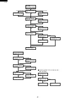
Excessive vibration
or Abnormal noise

At fan only mode,
Excessive vibration
 or Abnormal noise

Check the air filter

NO

OK

NG

OK

OK

OK

OK

OK

OK

OK

too big

NG

touching

NG

OK

NG

YES

not dirty

dirty

Clean the air filter.

Check the fan motor 
connector.

deform or broken

loosened

loosen

Measure the resistance 
of fan motor coil.

Change the fan motor.

Connect properly.

Change the fan

Tighten up.

Check rotating
direction of centrifugal
fan.(to clockwise)

Is the fan deformed or
broken.

Is  loosened screw
and nut fixing fan ?

Checking complete

Tighten up

Repair with adjusting
shape of pipes.

Repair mounting or
change compressor 
cushion.

Change compressor.

Is each screws
loosened ?

Is pipe touching to
another parts.

Check mounting of
compressor.

Check compressor
noise and vibration.

Checking complete

Summary of Contents for AF-06CSL

Page 1: ...OOTING GUIDE 26 COOLING LOAD ESTIMATE FORM 31 RUNNING CONDITION 33 PACKING AND ACCESSORIES 34 REPLACEMENT PARTS LIST 35 TABLE OF CONTENTS AIR CONDITIONER MODEL In the interests of user safety Required by safety regulations in some countries the set should be restored to its original condition and only parts identical to those specified should be used AF 06CSL SHARP CORPORATION This document has be...

Page 2: ...ary tube Refrigerant volume R 22 OZ 11 8 Factory change NET DIMENSIONS Width Height Depth inches mm 17 23 32 450 x 14 9 16 370 x 14 7 8 378 Net Weight lbs 48 GROSS DIMENSIONS Width Height Depth inches mm 20 7 8 530 x 18 1 8 460 x 18 3 8 467 Gross Weight lbs 54 FAN SYSTEM Indoor side Evaporator Centrifugal fan Outdoor side Condenser Propeller fan Air flow rate indoor side CFM High Med Low 195 175 1...

Page 3: ...F FAN MOTOR RUNNING CAPACITOR 250V 25µF THERMAL PROTECTOR BL BL BL BK BK BK GY RE OR WH COMPRESSOR MOTOR BK BL RE WH GR GY OR BLACK BLUE RED WHITE GREEN GRAY ORANGE POWER SUPPLY CORD 115V 60Hz 3A 125V IN GR MRY CONTROL BOARD UNIT NR C1 CN1 BCN2 BCN3 TR OUT RIBBED NON RIBBED BK BK C R RE WH GY BCN1 CN2 CN3 WH OR RE GY S FU1 1 2 3 6 5 4 WIRE COLOR YELLOW TH1 RY3 RY2 RY1 CNR3 CNR2 CNR1 THERMISTOR ROO...

Page 4: ...R indicator 0POWER ON OFF pad qPOWER indicator 3 4 5 6 7 8 9 10 11 1 2 PARTS NAMES UNIT CONTROL PANEL 1Front Cabinet 2Air Inlet Indoor Side 3Horizontal Louvers 4Vertical Louvers 5Air Outlet Indoor Side 6Control Panel 7Rear Cabinet 8Air Inlet Outdoor side 9Filter Pull the filter handle to the right to remove 0Filter Handle qPower Cord POWER ON OFF F hr SELECTOR TIMER ON OFF ENERGY SAVER COOL FAN TE...

Page 5: ...tting Temperature can be set within the range of 64 F to 86 F Display will change as you touch the pad NOTE The latest temperature setting will be memorized and will appear on the display the next time the unit is turned on In cases of power outages or when the unit is disconnected when the power is restored or the unit is plugged in the unit and display will return to the preset conditions of 74 ...

Page 6: ...tion mode will be memorized and the selector indicator and display will light when the unit is turned on In fan only operation the temperature display will go off When the SELECTOR is changed to fan only operation from cooling operation it will take 5 seconds for the compressor to stop COOL COOL COOL FAN FAN FAN MODE Cooling operation with high fan speed Cooling operation with medium fan speed Coo...

Page 7: ...cooling and the fan runs continuously When the ENERGY SAVER is selected the thermostat automatically controls cooling and the fan automatically stops when the compressor is not operating Fan will stop 30 seconds after the compressor stops After the fan stops the fan is programmed to rotate for approx 2 minutes to detect room temperature This will occur within a 20 min time span 2 Tocancel touchENE...

Page 8: ... advance of the start time or in 1 hour increments from 10 to 12 hours in advance of the start time The unit will start automatically according to your setting NOTES FOR TIMER SETTING AND OPERATION After setting the TIMER change the temperature and fan speed settings as shown on pages 11 and 12 When the temperature is set in the timer mode the temperature will show in the display for 5 seconds and...

Page 9: ...F pad to set the delayed stop time The time setting will change as you touch the pad The display will change as follows The timer will be set 5 seconds after the TIMER ON OFF pad is touched for the last time TIMER indicator will light The time display will count down the remaining time The unit will stop when the set time expires All indicators and displays will go out If you wish to stop the oper...

Page 10: ...t when not in use Front Cabinet Remote control hook Rear Cabinet HOW TO USE THE REMOTE CONTROL Point the remote control towards the unit s re ceiver window and press the desired button A beep will sound when the unit receives the signal Make sure no objects such as curtains block the receiver window The remote control operates from up to 20 feet 6 meters away The beep will also sound when each pad...

Page 11: ... unit s control panel See page 8 TEMP TEMP Raise temp setting 1 F at a time Lower temp setting 1 F at a time OPERATING WITH THE REMOTE CONTROL TRANSMITTER TEMPERATURE setting button POWER ON OFF button Push to start or stop the operation SELECTOR button Push to change fan speed and operation mode Fan speed and operation mode selec tions are shown to the right SET TIMER OFF button Push to set delay...

Page 12: ...6 Base pan angle 2 Remote control 1 Battery 2 Remote control hook 1 INSTALLATION WARNING Make sure the unit is turned off and unplugged before working 1 Cut the window sash foam seal adhesive type to the proper length and attach it to the underside of the window sash 2 Insert the right closure assembly and the left closure assembly into the top angle and the bottom channels Secure the right and le...

Page 13: ...a thin board or other hard filler 5 Insert the closure assemblies on both sides into the rails of the jamb 6 Loosen screws on both sides of the cabinet then hang the base pan angle on and secure the screws again 7 Secure the base pan angle to the sill by using the hole of the front side on the angle with one screw L 1 25 4mm 8 Secure the top angle of the unit and the top of the closure assemblies ...

Page 14: ...r 5 Remove the control panel 6 Unscrew the 5 screws 3 screws are holding the control box at the top and right side 1 screw is holding the power supply cord 1 screw each screw on the evaporator 7 Take off the fan motor connector 8 Unscrew the 1 screw holding the compressor cord 1 Unscrew the 2 screws holding the front panel on each side 2 Remove the front panel by pulling the front panel at the low...

Page 15: ...n left side 2 screws are on back side And remove the condenser from the unit 12 Unfasten the nut holding the propeller fan by rotating it counter clockise And remove the propeller fan 13 Unscrew the 3 screws holding the condenser shround And remove the condenser shround 14 Unscrew the 5 screws 2 screws are holding the evaporator on each side 3 screws are holding the bulkhead to the base pan on eac...

Page 16: ...16 AF 06CSL 17 Unscrew the screw holding the centrifugal fan Remove by using a driver or wrench 18 Remove the caseing 19 Unscrew the 4 screws holding fan motor ...

Page 17: ... printed wiring board 3 Cut the wire fixing bands holding the fan motor lead wires the compressor cord and the power supply cord 4 Unscrew the 1 screw holding the fan motor capacitor 5 Unscrew the 1 power supply cord grounding screw Unscrew the earth screw Unscrew the 1 screw holding the capacitor clamp 6 Detach each connector by using long noise pliers 7 Unscrew the 2 screws holding the transform...

Page 18: ...otherwise the alloy will not wet and flow properly over any surface with these elements present Cleaning can be done with an abrasive cloth or steel wool Never blow into the tubing because this will introduce a lot of moisture into the system Open tubing joints should be covered if exposed for long periods of time HOW TO REPAIR REFRIGERATION Before sealed system work can be preformed a refrigerant...

Page 19: ...es a smaller inner cone pale blue in calor and a much larger outer cone The hottest part of the flame is at the tip of the inner cone The flame should be directed at the joint with the tip of the cone just touching the surface of the tubing Figure 3 and 4 DEHYDRATING SEALED SYSTEM Many servicers feel that since air conditioners run with evaporator temperatures above 33 F moisture will not present ...

Page 20: ...ents and solder joints and if oil is found at any given location it generally is a sign that a leak exists at that point due to the fact that flame does carry oil with it travels through the system Soap Bubbles Liquid detergents can sometimes assist in finding small leaks by brushing detergent on the suspect area and watching for bubbles Before applying detergent be sure that the system is pressur...

Page 21: ...he indicator swings then returns a moment later Good INSULATION TEST Check the resistance between the terminals and case Reading must be more than 10MΩ at DC 500V OVERLOAD RELAY Check continuity between terminals with volt ohm meter INSULATION TEST Check resistance between terminals and the relay case Reading must be more than 10MΩ at DC 500V COMPRESSOR 1 Take the wires off compressor terminals 2 ...

Page 22: ... to 9 5 hours you can set by 0 5 hours increments and from 10 to 12 hours by 1 hour increment If you touch button POWER ON OFF during OFF TIMER operation then the unit turns off and OFF TIMER operation is cancelled 4 2 ON TIMER operation Set the delay timer when unit is not operating The unit will turn on automatically according to your setting Timer duration can be set by 0 5 hours to maximum 12 ...

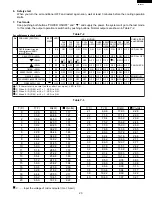
Page 23: ...POWER ON OFF and and supply the power the system will go to the test mode In this mode the output operation is switched by pushing buttons Normal outputs are shown in Table Y 2 Table Y 2 For selfdiagnosis check mode No PUSH KEY SWITCH PLUG IN the power supply cord while pushing power ON OFF key and down key BEPP SOUND LED1 8 8 ON OFF OFF ON OFF OFF ON OFF OFF OFF OFF OFF OFF OFF OFF OFF OFF OFF OF...

Page 24: ...5µF GRAY R S C COMPRESSOR MOTOR OVERLOARD PROTECTOR MRY 3A 125V FU1 C1 D1 D3 D4 D2 C2 C3 C4 C5 C6 C7 C8 0V Q5 R2 15K 250V 0 1µF NR 271 TR D1 D4 ZD1 HZ4A 2 25V 0 1µ 25V 47µ 25V 0 1µ 25V 0 1µ 25V 1000µ 25V 0 1µ 10V 100µ KRA101M DTA143ES COM 79L05 OUT IN 5V 12V R1 22K Q6 KRC101M DTC143ES R3 10K C10 C9 16V 0 01µ R4 20k 5V Q7 KRA106M DTA143ZS Q1 KRA105M DTA123JS Q7 R8 2 7K BZ Q1 Q2 Q3 Q4 OSC 5V 4MHz C1...

Page 25: ...25 AF 06CSL Printed Wiring Board BCN2 R15 QPWBFB438JBZZ DPWBFA244JBKZ QPWBFB438JBZZ DPWBA244JBKZ ...

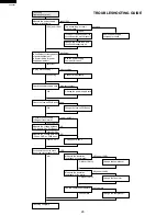
Page 26: ...WB ass y If unit operate dose the house fuse or the circuit breaker open Checking complete 120V over 100V NG under 10MΩ OK over 10MΩ NG under 10MΩ OK over 10MΩ can operate can t operate under 100V open The house fuse or circuit breaker open Is it proper current capacity of the house fuse or the circuit breaker Ask the power supply company for check Change the house fuse and the circuit breaker tur...

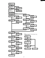
Page 27: ...rrent in compressor circuit Is it sufficient current capacity of power equipment Is it small wiring for power supply equipment Measure the power supply voltage at receptacle Check the overload relay Check the overload relay Is the connector disconnecting Check the compressor relay MRY on PWB Check the thermister Measure the resistance of its coil Turn on the power supplty as operating the compress...

Page 28: ...urn off the power supply Measure the contact resistance short open OK NG Change the thermister Change PWB ass y The compressor doesn t turn off Check the thermister connector Check the thermister resistance Check the compressor relay OK NG disconnecting OK OK NG Checking complete Change the fan motor capacitor Change the fan motor Is the fan touched to another parts Change the fan motor Change fan...

Page 29: ...charge the refrigerant The compressor is defective Change the compressor The capillary tube restrict and change the capillary tube Measure the emperature difference between discharge tube and suction tube Is frost sticking to capillary tube Or is indoor heat exchanger no cold Check the air filter Is there high heat source or any object restricting heat radiation near the unit Check doors and windo...

Page 30: ...ure the resistance of fan motor coil Change the fan motor Connect properly Change the fan Tighten up Check rotating direction of centrifugal fan to clockwise Is the fan deformed or broken Is loosened screw and nut fixing fan Checking complete Tighten up Repair with adjusting shape of pipes Repair mounting or change compressor cushion Change compressor Is each screws loosened Is pipe touching to an...

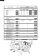
Page 31: ...es or less in thickness is considered Light Construction An insulated frame wall or a masonry wall over 8 inches in thickness is considered Heavy Construction 3b Multiply the total length linear feet of all inside walls between the space to be conditioned and any unconditioned spaces by the given factor Do not include inside walls which separate other air conditioned rooms 4 Multiply the total squ...

Page 32: ... 14 7 8 3 3 3 5 600 300 Light Construction Heavy Construction x x x x x x x x x x Item 9 x Factor from Map 3 WALLS Based on linear feet of wall 4 ROOF OR CEILING Use one only 5 FLOOR Disregard if floor is directly on ground or over basement 6 NUMBER OF PEOPLE 7 LIGHTS AND ELECTRICAL EQUIPMENT IN USE 8 DOORS AND ARCHES CONTINUOUSLY OPENED TO UNCONDITIONED SPACE Linear feet of width 9 SUB TOTAL 10 T...

Page 33: ...nditioner above or below this rating the data may miss the range of the performance curve 3 Outlet air temp is influenced by the method of measurement Measurement examples are shown 4 Use power input data when checking the Running Condition PERFORMANCE CURVE Outside air temp C F Outlet air temp C F 25 30 35 77 86 95 104 40 10 20 30 50 68 86 4 5 6 500 400 600 Line current Amp Power input W 700 40 R...

Page 34: ... Bottom gasket Screws Base pan angle Right closure assembly Left closure assembly Remote control Battery Remote control hook 3 2 Packing case SPAKCB002JBEZ Front side Front side mark 6 5 6 5 Bottom pad assembly CPADBA046JBKZ Power supply cord Protect SSAKHA245YDE0 Energy star label TLAB C277JBRZ 1 Enegry card TLAB C218JBEZ Detail is assembling Energy card ...

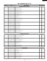
Page 35: ... Number card 1 AC 1 31 TLABMA326JBRZ Feature card 1 AE 1 32 TLAB C277JBRZ Energy star label 1 AE 1 33 LBND A042JBE0 Wire fixing band 2 AC 1 34 DSKR A126JBKZ Bulkhead ass y 1 AW 1 35 DKES A029JBKZ Orifice ass y 1 AW CONTROL BOX PARTS 2 1 DPLT A057JBWZ Cont box cover ass y 1 AH 2 2 DPLT A058JBWZ Cont box angle ass y 1 AM 2 3 LBNDKA104JBWZ Capacitor clamp 1 AG 2 4 QACC A260JBZZ Power supply cord 1 AS...

Page 36: ...Wood screw 7 AA 4 13 LANGAA030JBTA Base pan angle 2 AD 4 14 CRMC A526JBEZ Remote control 1 AT 4 15 LHLD A389JBFB Controller holder 1 AC 4 16 SPADBA163JBEZ Card board 1 AC 4 17 SSAKHA009JBEZ Bag 1 AC 4 18 UBATUA027JBE0 Battery pack 1 AE PACKING PARTS 5 1 DPADBA004JBFZ Top pad ass y 1 AH 5 2 CPADBA046JBKZ Bottom pad ass y 1 AN 5 3 SPAKCB002JBEZ Packing case 1 AP 5 4 SSAKHA245YDE0 Protect 1 AB 5 5 SS...

Page 37: ...8 4 3 4 2 6 4 1 3 6 9 1 29 6 9 1 2 6 11 5 3 1 30 5 4 5 5 6 8 1 14 1 15 6 4 6 3 6 3 1 1 6 4 6 3 1 23 1 27 6 2 1 28 1 32 6 2 1 22 1 21 1 19 1 17 1 16 1 31 2 4 5 2 1 9 1 8 6 13 6 11 1 4 6 4 1 7 6 1 6 1 6 4 1 33 1 24 1 26 1 26 1 25 6 3 1 13 1 12 1 10 1 11 1 34 6 5 6 5 6 4 6 10 5 1 4 5 4 6 4 7 4 4 4 11 4 12 4 13 1 35 1 18 1 20 ...

Page 38: ...F 06CSL 1 6 1 5 6 7 6 12 6 6 6 4 2 8 2 3 6 5 2 16 2 10 2 5 2 13 2 14 6 6 6 4 6 6 2 9 2 1 2 6 2 4 6 5 2 7 2 11 2 12 2 2 2 10 6 7 2 17 1 2 3 4 5 1 2 3 4 5 6 6 A B C D E F G H A B C D E F G H CONTROL BOX PARTS ...

Page 39: ...39 AF 06CSL 1 2 3 4 5 1 2 3 4 5 6 6 A B C D E F G H A B C D E F G H CYCLE PARTS 6 14 3 13 3 12 3 11 3 10 3 9 3 15 3 4 3 8 3 1 3 5 3 6 3 14 3 7 3 2 6 5 6 15 3 16 6 3 6 15 3 3 2 15 ...

Page 40: ... BY SHARP CORPORATION ALL RIGHTS RESERVED No part of this publication may be reproduced stored in retrieval systems or transmitted in any form or by any means electronic mechanical photocopying recording or otherwise without prior written permission of the publisher ...

Reviews: