AYXPC18LR
5 – 6
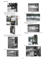
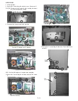
7. Cut the insulators.
8. Remove the 2 screws fixing the control box cover, then remove it.
CAUTION: Discharge electrytic capacitor before touching this capaci-
tor or other components or wirings.
9. Disconnect the 4 connectors and the 3 terminals.
Fan motor / Expansion valve / Thermistor
NOTE: Caution to the position of connectors when reinstalling.
10.Remove the 5 screws fixing the controlbox assembly, then remove
it.
11.Remove the 11 screws fixing the side cover R and slide the side
cabinet R.
Cut
Control box cover
Fan motor
Thermistor
Coil of reverse valve
Coil of expansion
valve
Thermistor
Red (U)
White (V)
Orange (W)
Control Box Assembly
Control box
assembly
Side
cabinet R
Side
cabinet R


