45
Condition:
User controls are set to the initial set
positions (for shipment)
Measuring point-Screen center.
STICKING OUT OF BLUE
Defocus sticking out specification
Screen Size Blue sticking out
53Ó
1.0mm
60Ó
1.0mm
2.13 Blue defocus adjustment
Adjustment Preparation
(1) Optical and electrical focus adjustment should
have been completed.
(2) The convergence adjustment should have been
completed.
(3) Set Video conditions to factory preset.
(4) Input the cross-hatch signal.
Adjustment procedure
(1) Short-circuit 2P sub-mini connectors on the red
and green CPT P.W.Bs. to display only the blue
beam.
(2) Turn the B Focus VR (Focus Pack) fully
clockwise.
(3) Adjust the BLUE focus VR counter-clockwise
so that the sticking out part of blue satisfies the
specification.
Adjustment preparation
(1) Start adjustment after the power is turned on for
20 minutes or more.
(2) The vertical incident illumination on the screen
should be 20 lux or less. (Room should be dark).
(3) Set the video settings (CONTRAST: max,
others: center) to standard condition.
(4) The blue defocus and cut off adjustments should
be completed.
2.14 White balance adjustment
(1) Screen adjustment
(2) High light white balance.
(3) Low light balance.
Screen adjustment VRs
Red:
on FOCUS PACK
Green: on FOCUS PACK
Blue: on FOCUS PACK
Drive adjustment VRs
Red:
R829 on CPT P.W.B.
Green: R879 on CPT P.W.B.
(5) For low light white balance adjustment, input a
white raster signal level of 0.286 Vp-p (Video
input level).
(6) For high light white balance adjustment, input a
white raster signal level of 0.715Vp-p (Video
input level).
(7) Set the drive adjustment VRs (red and green) to
12 - 2 oÕclock position.
(8) Set Video Advanced Settings-Color temperature
to COOL.
Adjustment procedure
(1) Select the input signal for high brightness (Video
level = 0.715Vpp).
(2) Adjust the high brightness white balance, to
10800ûK±0MPCD (x=0.278, 0.280) at center of
the screen, using the drive adjustment VRs (red,
green) on the CPT P.W.B.
(3) Select the signal for low brightness (Video level
= 0.286Vpp)
(4) Adjust the low brightness white balance using
the screen adjustment VRs (red, green, blue) on
the FOCUS PACK. (Visually adjust).
(5) Check that high brightness white balance is still
obtained. If it is not, return to step (2).
NOTE:
When adjusting low level white balance, turn the
screen VRs counterclockwise. The cut-off
adjustment should already be completed and
the screen VRÕs should not be increased past
the level set at cut-off. Since the
phosphorescent surface of the CRT is likely to
be burned, be careful. Do not turn the screen
VRÕs clockwise.
White balance =
10800¡ K ± 0 MPCD
Color coordinate =
x ÉÉ 0.278
y ÉÉ 0.280
2.15 Sub brightness adjustment
Adjustment preparation
(1) Start adjustment after the power is turned ON
for 20 minutes or more.
(2) Receive the color bar signal.
(3) Set video conditions to factory preset.
(4) The vertical incident illumination on the screen
should be 20 lux or less. (Room should be dark).
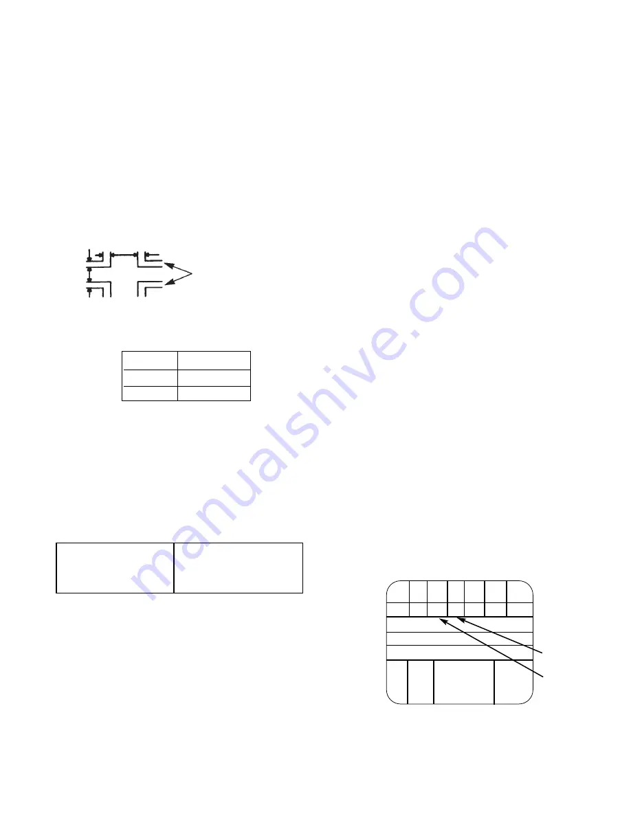
Should sink
to black
Should rise
slightly from
black
Y
CY G MG R BL
A7 A6
A5 A4 A3 A2
A1
B
C
D
Q I
W
100%
BLK
W
75%
Summary of Contents for 50NP4
Page 55: ...55 ...
Page 56: ...56 ...
Page 57: ...57 ...
Page 64: ...PRINTED CIRCUIT BOARD 61 2H Video Terminal P W B ...
Page 65: ...PRINTED CIRCUIT BOARD DEFLECTION P W B 62 ...
Page 66: ...PRINTED CIRCUIT BOARD SIGNAL P W B 63 ...
Page 67: ...PRINTED CIRCUIT BOARD VM SENSOR 2 64 ...
Page 68: ...PRINTED CIRCUIT BOARD POWER SUPPLY P W B 65 ...
Page 69: ...PRINTED CIRCUIT BOARD SRS P W B 66 ...
Page 70: ...67 WIRING DRESS DRAWING ...
Page 71: ...68 50NP4 WIRING DRAWING ...
Page 72: ...69 60NP4 WIRING DRAWING ...
Page 73: ...70 50NP4 WIRING DRAWING ...
Page 74: ...71 60NP4 WIRING DRAWING ...
Page 75: ...72 BLOCK DIAGRAM ...
Page 76: ...73 WIRING DRAWING ...
Page 90: ...88 ...


