background image

12

11

10

9

8

7

6

5

4

3

2

1

A

B

C

D

E

F

G

H

36K-X2000 CK36S60

32K-X2000 CK32S60

36K-X2000 CK36S60

32K-X2000 CK32S60

21

22

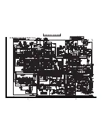
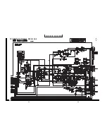
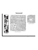
SCHEMATIC DIAGRAM : MAIN-1 Unit

Summary of Contents for 32K-X2000

Page 1: ...T 57 Page CONTENTS AUDIO POWER OUTPUT RATING 3W 3W at 10 distortion and Dual CH Operate SPEAKER SIZE 12 x 6 cm 2 pcs VOICE COIL IMPEDANCE 6 ohm at 400 Hz ANTENNA INPUT IMPEDANCE VHF UHF 75 ohm Unbalanced TUNING RANGES VHF Channels 2 thru 13 UHF Channels 14 thru 69 CATV Channels 1 thru 125 EIA Channel Plan U S A POWER INPUT 120V AC 60 Hz POWER RATING 32K X2000 CK32S60 150W 36K X2000 CK36S60 165W PI...

Page 2: ...voltage with a meter to be certain that the high voltage does not exceed the specified value and that it is regulating correctly 5 Do not use a picture tube other than that specified or make unrecommended circuit modifications to the high voltage circuitry 6 When trouble shooting and taking test measurements on a receiver with excessive high voltage avoid being unnecessarily close to the receiver ...

Page 3: ...nt and compartment covers or shields isolation resistor capacity networks mechanical insulators etc 3 To be sure that no shock hazard exists check for leakage current in the following manner Plug the AC cord directly into a 120 volt AC outlet Do not use an isolation transformer for this test Using two clip leads connect a 1 5k ohm 10 watt resistor paralleled by a 0 15µF capacitor in series with al...

Page 4: ...te tension qui doit être périodiquement étalonné 3 La haute tension doit toujours être maintenue à la valeur de régime et pas plus haute L opération à des tensions plus élevées peut entraîner une panne du tube image ou du circuit à haute tension et dans certaines conditions peut entraîner une radiation dépassant les niveaux préscrits 4 Quand le régulateur à haute tension fonctionne correctement il...

Page 5: ...e compartiment les réseaux de résistance capacité les isolateurs mécaniques etc 3 S assurer qu il n y ait pas de danger d électrocution en vérifiant la fuite de courant de la facon suivante Brancher le cordon d alimentation directem ent à une prise de courant de 120V Ne pas utiliser de transformateur d isolation pour cet essai A l aide de deux fils à pinces brancher une résistance de 1 5 kΩ 10 wat...

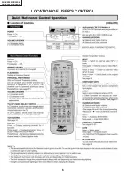
Page 6: ...6 36K X2000 CK36S60 32K X2000 CK32S60 LOCATION OF USER S CONTROL ...

Page 7: ...horizontal oscillator does not stop in step 5 the circuit must be repaired before the set is returned to the customer HIGH VOLTAGE CHECK High voltage is not adjustable but must be checked to verify that the receiver is operating within safe and efficient design limitations as specified checks should be as follows 1 Connect an accurate high voltage meter between ground and anode of picture tube 2 O...

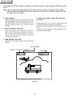
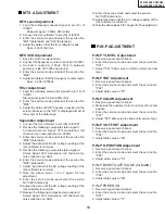
Page 8: ...ction in the video adjustment menu to ensure customer controls are in their proper reset position 2 Service Number Selection Once in the service mode press the Ch up or Ch down button on the remote controller or at the set The service adjustment number will vary in increments of one from S01 to G06 Select the item you wish to adjust 3 Data Number Selection Press the Vol up or down button to adjust...

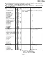
Page 9: ...S25 DC RESTORATION RATE 00 63 21 21 S26 DC RESTORATION LIMIT 00 03 0 00 S27 BLACK STRETCH POINT 00 07 3 03 S28 APL VS BPS 00 03 1 01 S29 B L C 00 01 1 01 S30 DYNAMIC ABL POINT 00 07 4 04 S31 DYNAMIC ABL GAIN 00 07 4 04 S32 ABL POINT 00 07 3 03 S33 ABL GAIN 00 07 3 03 S34 Y DL 00 01 1 00 S35 TOF f0 00 07 4 07 S36 TOF Q 00 07 4 04 S37 VSM GAIN 00 03 1 01 S38 OSD SL 00 01 0 00 S39 C DECODE 00 255 105...

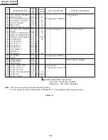
Page 10: ...00 C06 V POSITION C 00 07 0 00 C07 H POSITION C 00 31 19 C08 R CUT OFF C 00 255 64 C09 G CUT OFF C 00 255 64 C10 B CUT OFF C 00 255 64 C11 G R DRIVE C 00 127 64 C12 B DRIVE C 00 127 64 C13 VSM GAIN C 00 03 2 02 A01 PICTURE 2 00 31 28 RF signal input TUNER A A02 TINT 2 00 63 20 A03 INPUT LEVEL 2 00 15 7 MTS IC IC3001 adjusted A04 WIDE BAND 2 00 63 17 A05 SPECTRAL 2 00 63 22 G01 TVGP OSD H POS1 16 5...

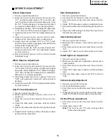
Page 11: ...t 1 Receive a good local channel 2 Make sure the customer picture control is set to maximum 3 Enter the service mode and select the service No S09 4 Adjust the data value to achieve normal contrast range 5 Receive the same local channel through the antenna A 6 Adjust the A01 setting to achieve the same contrast as that with the antenna B Sub TintAdjustment 1 Receive a good local channel 2 Set cust...

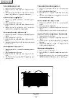
Page 12: ... 3 Enter the service mode and select the service No S04 4 Vary the data of service No S04 to obtain the best horizontal size TrapezoidalDistortionAdjustment 1 Receive a good CATV channel or crosshatch pattern signal 2 Set to standard setting mode 3 Enter the service mode and select the service No S07 4 Adjust so that the leftmost and rightmost vertical lines are parallel to each other Corner Disto...

Page 13: ...until the AC voltage reading of the rms voltmeter is minimum 8 Take the above steps 1 thru 7 again for fine adjustment 9 Enter the service mode and select the service No A04 Antenna A 10 Adjust the data until the AC voltage reading of the rms voltmeter is minimum 11 Receive the following composite stereo signal 2 Stereo signal 30 modulation left channel only noise reduction on 3kHz 12 Enter the se...

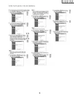
Page 14: ...PIP is centered in the display frame of the screen 2 V position Adjustment Input a good channel intoAntenna B and another into Antenna A Enter the Service Mode and select ServiceAdjustment G03 GUIDE PLUS OSD is displayed on the screen Enable adjustment of the G03 data bus and adjust so that the vertical position of GUIDE PLUS PIP is centered in the display frame of the screen 4 GUIDE Plus Data Che...

Page 15: ...15 32K X2000 CK32S60 36K X2000 CK36S60 Confirm the IR operation in the order listed below ...

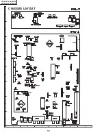
Page 16: ...16 36K X2000 CK36S60 32K X2000 CK32S60 H G F E D C B A 1 2 3 4 5 6 CHASSIS LAYOUT ...

Page 17: ... B A 1 2 3 4 5 6 PWB B Q 1 5 0 6 P A Y B N E B Q 1 5 0 7 E B Q 8 5 2 E B Q 8 5 0 Q 8 5 1 B E E B C J G B N P U N G R K 8 5 4 K 8 5 2 S C 8 5 1 Q 8 9 1 Q 8 5 5 Q 8 9 0 Q 8 9 4 7 0 1 T P 4 8 R Q 1 5 0 4 Q 1 5 0 5 Q 8 5 3 Q 8 5 4 K 8 5 7 R 8 8 0 T P 4 7 R ...

Page 18: ... and all controls set for normal picture unless otherwise indicated 2 All voltages measured with 1000µ V B W or Color signal WAVEFORM MEASUREMENT CONDITIONS 1 Photographs taken on a standard gated color bar signal the tint setting adjusted for proper color The wave shapes at the red green and blue cathodes of the picture tube depend on the tint color level and picture control 2 indicates waveform ...

Page 19: ...12 11 10 9 8 7 6 5 4 3 2 1 A B C D E F G H 36K X2000 CK36S60 32K X2000 CK32S60 36K X2000 CK36S60 32K X2000 CK32S60 BLOCK DIAGRAM 19 20 ...

Page 20: ...12 11 10 9 8 7 6 5 4 3 2 1 A B C D E F G H 36K X2000 CK36S60 32K X2000 CK32S60 36K X2000 CK36S60 32K X2000 CK32S60 21 22 SCHEMATIC DIAGRAM MAIN 1 Unit ...

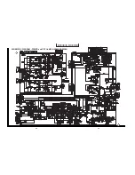
Page 21: ...12 11 10 9 8 7 6 5 4 3 2 1 A B C D E F G H 36K X2000 CK36S60 32K X2000 CK32S60 36K X2000 CK36S60 32K X2000 CK32S60 23 24 SCHEMATIC DIAGRAM MAIN 2 and CONTROL Unit ...

Page 22: ...12 11 10 9 8 7 6 5 4 3 2 1 A B C D E F G H 36K X2000 CK36S60 32K X2000 CK32S60 36K X2000 CK36S60 32K X2000 CK32S60 25 26 SCHEMATIC DIAGRAM MAIN 3 Unit ...

Page 23: ...12 11 10 9 8 7 6 5 4 3 2 1 A B C D E F G H 36K X2000 CK36S60 32K X2000 CK32S60 36K X2000 CK36S60 32K X2000 CK32S60 27 28 SCHEMATIC DIAGRAM POWER and CRT Unit 32K X2000 CK32S60 ...

Page 24: ...12 11 10 9 8 7 6 5 4 3 2 1 A B C D E F G H 36K X2000 CK36S60 32K X2000 CK32S60 36K X2000 CK36S60 32K X2000 CK32S60 29 30 SCHEMATIC DIAGRAM POWER and CRT Unit 36K X2000 CK36S60 ...

Page 25: ... 2 1 A B C D E F G H 36K X2000 CK36S60 32K X2000 CK32S60 36K X2000 CK36S60 32K X2000 CK32S60 SCHEMATIC DIAGRAM TV GUIDE Unit PRINTED WIRING BOARD ASSEMBLIES PWB G TV GUIDE Unit Chip Side PWB G TV GUIDE Unit Wiring Side 31 32 ...

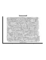
Page 26: ...12 11 10 9 8 7 6 5 4 3 2 1 A B C D E F G H 36K X2000 CK36S60 32K X2000 CK32S60 36K X2000 CK36S60 32K X2000 CK32S60 33 34 PWB A MAIN Unit Wiring Side ...

Page 27: ...12 11 10 9 8 7 6 5 4 3 2 1 A B C D E F G H 36K X2000 CK36S60 32K X2000 CK32S60 36K X2000 CK36S60 32K X2000 CK32S60 35 36 PWB A MAIN Unit Chip Parts Side ...

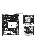
Page 28: ...11 10 9 8 7 6 5 4 3 2 1 A B C D E F G H 36K X2000 CK36S60 32K X2000 CK32S60 36K X2000 CK36S60 32K X2000 CK32S60 37 38 PWB F CONTROL Unit Wiring Side PWB B CRT Unit Wiring Side PWB C POWER Unit Wiring Side ...

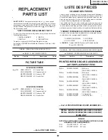
Page 29: ...it rapidement et correctement remplie veuillez fournir les renseignements suivants 1 NUMERO DU MODELE 2 NO DE REF 3 NO DE PIECE 4 DESCRIPTION in CANADA Contact SHARP Electronics of Conada Limited Phone 416 890 2100 MARQUE SECTION LIVRAISON DES PIECES DE RECHANGE MARQUE PIECES RELATIVE AUX RAYONS X PICTURE TUBE TUNER NOTE THE PARTS HERES SHOWN ARE SUPPLIED AS AN ASSEMBLY NOT INDEPENDENTLY TU51 VTUV...

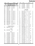
Page 30: ...1AR 1 J 2SD601 AC Q1407 VS2SB709AR 1 J 2SB709 AC Q1408 VS2SB709AR 1 J 2SB709 AC Q1409 VS2SD601AR 1 J 2SD601 AC Q1410 VS2SB709AR 1 J 2SB709 AC Q1411 VS2SB709AR 1 J 2SB709 AC Q1412 VS2SD601AR 1 J 2SD601 AC Q1434 VS2SB709AR 1 J 2SB709 AC Q1435 VS2SD601AR 1 J 2SD601 AC Q1436 VS2SD601AR 1 J 2SD601 AC Q1450 VS2SD601AR 1 J 2SD601 AC Q1721 VS2SD601AR 1 J 2SD601 AC Q1741 VS2SD601AR 1 J 2SD601 AC Q1742 VS2S...

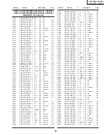
Page 31: ...king 10µH AB L1822 VP XF100K0000 J Peaking 10µH AB L1861 VP XF100K0000 J Peaking 10µH AB L1862 VP XF100K0000 J Peaking 10µH AB L1863 VP XF100K0000 J Peaking 10µH AB L2001 VP XF100K0000 J Peaking 10µH AB L2002 VP MK100K0000 J Peaking 10µH AB T2001 RCiLB0158CEZZ M Oscillation Coil CAPACITORS EL Electrolytic C51 VCKYPA1HF103Z J 0 01 50V Ceramic AA C52 VCEA0A1CW108M J 1000 16V EL AD C54 VCEA0A1HW105M ...

Page 32: ...4K J 0 1 16V Ceramic AB C1319 VCE9GA1CW106M J 10 16V EL_ N P AB C1320 VCKYCY1HB271K J 270p 50V Ceramic AA C1321 VCKYCY1HB271K J 270p 50V Ceramic AA C1322 VCKYCY1CB104K J 0 1 16V Ceramic AB C1323 VCKYCY1HF103Z J 0 01 50V Ceramic AA C1324 RC QZA104TAYK J 0 1 50V Mylar AB C1325 VCEA0A1CW226M J 22 16V EL AB C1326 VCEA0A1CW107M J 100 16V EL AC C1327 VCKYCY1HB271K J 270p 50V Ceramic AA C1328 VCKYCY1HB27...

Page 33: ...16V Ceramic AB C1849 VCEA0A1HW106M J 10 50V EL AB C1850 VCKYCY1CB104K J 0 1 16V Ceramic AB C1851 VCKYCY1HF103Z J 0 01 50V Ceramic AA C1861 VCKYCY1CB104K J 0 1 16V Ceramic AB C1862 VCKYCY1CB104K J 0 1 16V Ceramic AB C1863 VCCCCY1HH101J J 100p 50V Ceramic AA C1865 RC QZA154TAYJ J 0 15 50V Mylar AC C1866 RC QZA103TAYJ J 0 01 50V Mylar AB C1867 VCKYCY1CB104K J 0 1 16V Ceramic AB C1868 VCFYSA1HB474J J ...

Page 34: ... 50V Mylar AA C3323 VCFYSA1HB474J J 0 47 50V Mylar AC RESISTORS M Ox Metal Oxide M Film Metal Film RJ1 VRS CY1JF000J J 00 1 16W M Ox AA RJ2 VRS CY1JF000J J 00 1 16W M Ox AA RJ3 VRS CY1JF000J J 00 1 16W M Ox AA RJ4 VRS CY1JF000J J 00 1 16W M Ox AA RJ5 VRS CY1JF000J J 00 1 16W M Ox AA RJ6 VRS CY1JF000J J 00 1 16W M Ox AA RJ7 VRS CY1JF000J J 00 1 16W M Ox AA RJ8 VRS CY1JF000J J 00 1 16W M Ox AA RJ9 V...

Page 35: ...R0J M 1 0 1 2W M Film R782 VRS VV3DB330J J 33 2W M Ox AA R783 VRD RA2BE122J J 1 2k 1 8W Carbon AA R784 VRS RG3LB100J M 10 3 0W M Ox R785 VRD RA2BE180J J 18 1 8W Carbon AA R803 VRS CY1JF101J J 100 1 16W M Ox AA R807 VRD RA2BE102J J 1 0k 1 8W Carbon AA R814 VRS CY1JF332J J 3 3k 1 16W M Ox AA R817 VRS CY1JF273J J 27k 1 16W M Ox AA R820 VRD RA2BE101J J 100 1 8W Carbon AB R821 VRD RA2BE101J J 100 1 8W ...

Page 36: ... AA R1440 VRS CY1JF473J J 47k 1 16W M Ox AA R1441 VRS CY1JF224J J 220k 1 16W M Ox AA R1442 VRS CY1JF103J J 10k 1 16W M Ox AA R1443 VRS CY1JF103J J 10k 1 16W M Ox AA R1444 VRD RA2BE182J J 1 8k 1 8W Carbon AA R1445 VRS CY1JF103J J 10k 1 16W M Ox AA R1446 VRD RA2BE101J J 100 1 8W Carbon AB R1447 VRS CY1JF153J J 15k 1 16W M Ox AA R1450 VRS CY1JF273J J 27k 1 16W M Ox AA R1452 VRS CY1JF562J J 5 6k 1 16W...

Page 37: ...6W M Ox AA R2036 VRS CY1JF102J J 1 0k 1 16W M Ox AA R2037 VRS CY1JF102J J 1 0k 1 16W M Ox AA R2038 VRS CY1JF223J J 22k 1 16W M Ox AA R2039 VRS CY1JF102J J 1 0k 1 16W M Ox AA R2040 VRS CY1JF223J J 22k 1 16W M Ox AA R2041 VRS CY1JF682J J 6 8k 1 16W M Ox AA R2042 VRS CY1JF153J J 15k 1 16W M Ox AA R2043 VRS CY1JF102J J 1 0k 1 16W M Ox AA R2044 VRD RA2BE103J J 10k 1 8W Carbon AA R2045 VRS CY1JF103J J 1...

Page 38: ...k 1 16W M Ox AA R3321 VRS CY1JF114J J 110k 1 16W M Ox AA R3322 VRS CY1JF102J J 1 0k 1 16W M Ox AA MISCELLANEOUS PARTS J1301 QTANJ0821CEZZ J Terminal Video Audio in AL J1302 QSOCD0430CEZZ J Socket Video 1 S VIDEO AE J1303 QSOCD0430CEZZ J Socket Video 2 S VIDEO AE J1701 QTANJ0527CEZZ J Terminal Component in AH J2001 QJAKA0022CEZZ J Jack IR AC P109 QPLGN0661CEZZ J Plug 6 Pin EJ AD P351 QPLGN0461CEZZ ...

Page 39: ... VRD RA2BE561J J 560 1 8W Carbon AA R853 VRS VV3DB183J J 18k 2W M Ox AA R854 VRS VV3DB183J J 18k 2W M Ox AA R855 VRS VV3DB183J J 18k 2W M Ox AA R856 VRD RA2BE820J J 82 1 8W Carbon AA R857 VRD RA2BE820J J 82 1 8W Carbon AA R858 VRD RA2BE820J J 82 1 8W Carbon AA R859 VRD RA2BE680J J 68 1 8W Carbon AA R865 VRS VV3DB153J J 15k 2W M Ox AA R866 VRS VV3DB153J J 15k 2W M Ox AA R867 VRS VV3DB153J J 15k 2W ...

Page 40: ...ZZ J Diode AC D621 RH EX0631GEZZ J Zener Diode 9 1V AA D622 RH DX0131CEZZ J Diode AC åD651 RH DX0130CEZZ J Diode AE åD652 RH EX0641GEZZ J Zener Diode 12V AA åD653 VHD1SS119 1 J Diode AB åD654 VHD1SS119 1 J Diode AB åD673 RH DX0229CEZZ J Diode AF or RH DX0449CEZZ D705 VHD1SS82 1A J Diode AC D706 RH DX0130CEZZ J Diode AE D707 VHD1SS82 1A J Diode AC D708 RH DX0130CEZZ J Diode AE åD709 RH DX0229CEZZ J...

Page 41: ...2AA564J J 0 56 100V Mylar AD C517 VCFYHA1HA473J J 0 047 50V Mylar AB C518 VCFYHA1HA473J J 0 047 50V Mylar AB C519 VCEA0A1VW108M J 1000 35V EL AD 32K X2000 CK32S60 C519 VCEA0H1VW228M J 2200 35V EL AH 36K X2000 CK36S60 C520 VCEACA1HC105J J 1 0 50V EL AB C521 VCEACA1HC105J J 1 0 50V EL AB C530 VCEA0A1VW476M J 47 35V EL AB C533 VCFYSA1JA473J J 0 047 63V Mylar AC 32K X2000 CK32S60 C533 VCFYAA2AA104K J ...

Page 42: ...7 VRD RA2BE823J J 82k 1 8W Carbon AA R520 VRD RA2BE181J J 180 1 8W Carbon AA R521 VRD RA2BE562J J 5 6k 1 8W Carbon AA R522 VRS RG3AB102J M 1 0k 1W M Ox R523 VRD RA2BE183J J 18k 1 8W Carbon AA R524 VRD RM2HD152J J 1 5k 1 2W Carbon AA R525 VRD RA2BE473J J 47k 1 8W Carbon AA R527 VRD RA2BE103J J 10k 1 8W Carbon AA R529 VRD RA2BE273G J 27k 1 8W Carbon AA 32K X2000 CK32S60 R529 VRD RA2BE333G J 33k 1 8W...

Page 43: ...RS RG3AB182J J 1 8k 1W M Ox AA R726 VRS RG2HC102J J 1 0k 1 2W M Ox AA 36K X2000 CK36S60 R734 VRS RG3LB223J M 22k 3 0W M Ox R737 VRN RL3DBR56J M 0 56 2W M Film R751 VRD RA2BE473J J 47k 1 8W Carbon AA R753 VRS RG3AB391J M 390 1W M Ox R760 VRD RA2EE822J J 8 2k 1 4W Carbon AA SWITCH S502 QSW B0015CEZZ J V Center AC MISCELLANEOUS PARTS åRY701 RRLYU0036CEZZ J Relay AM or RRLYU0038CEZZ åRY702 RRLYU0038CE...

Page 44: ...S RJ1 VRS CY1JF000J J 00 1 16W M Ox AA RJ2 VRS CY1JF000J J 00 1 16W M Ox AA R2101 VRS CY1JF104J J 100k 1 16W M Ox AA R2102 VRS CY1JF561J J 560 1 16W M Ox AA R2103 VRS CY1JF680J J 68 1 16W M Ox AA R2104 VRS CY1JF271J J 270 1 16W M Ox AA R2105 VRS CY1JF1R0J J 1 0 1 16W M Ox AA R2106 VRS CY1JF105J J 1 0M 1 16W M Ox AA R2107 VRS CY1JF152J J 1 5k 1 16W M Ox AA R2108 VRS CY1JF332J J 3 3k 1 16W M Ox AA R...

Page 45: ...7CEZZ J Ferrite Bead AB FB2102 RBLN 0037CEZZ J Ferrite Bead AB FB2103 RBLN 0037CEZZ J Ferrite Bead AB FB2104 RBLN 0037CEZZ J Ferrite Bead AB P2106 QPLGN0785CEZZ J Plug AC P2107 QPLGN1085CEZZ J Plug AC P2108 QPLGN0685CEZZ J Plug AA SLD2102 PSLDM0015MEFW M Shield AA DIODES D4002 RH PX0383CEZZ J LED Power AC D4003 RH PX0383CEZZ J LED V LIM AC CAPACITOR C4001 VCEA0A1HW475M J 4 7 50V EL AB RESISTORS R4...

Page 46: ...ACCESSORIES SPAKC0606MEZZ Packing Case _ 32K X2000 CK32S60 SPAKC0604MEZZ Packing Case _ 36K X2000 CK36S60 SPAKX0171MEZZ Buffer Material _ 32K X2000 CK32S60 SPAKX0172MEZZ Buffer Material _ 36K X2000 CK36S60 SSAKA0004MEZZ Polyethylene Sack _ TGAN 1006MEZZ M Guarantee Card AA TiNS 6412MEZZ M Oparation Manual RRMCG1418CESA M Infrared R C Unit AN CABINET PARTS CABINET PARTS LOCATION End of CABINET PART...

Page 47: ...OF THE SET REAR Use 2 tape fix the packing case Bar Code Label Packing Case Serial Number Label MARK Not replacement items Number Card FRONT Buffer Material Polystyrene Sack Polystyrene Bag Infrared R C unit Operation Manual Guarantee Card Batteries ...

Page 48: ...e reproduced stored in a retrieval system or transmitted in any form or by any means electronic mechanical photocopying recording or otherwise without prior written permission of the publisher TQ0000 S Oct 1998 Printed in Japan SY SHARP CORPORATION AV Systems Group Quality Reliability Control Center Yaita Tochigi 329 2193 Japan ...

Reviews: