background image

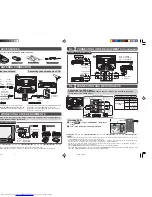
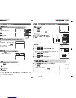
If your outdoor antenna uses a 75-ohm coaxial
cable with a standard DIN45325 plug (IEC 169-2),
plug it into the antenna jack at the rear of the set.

Connecting to an antenna

Connecting to an antenna via a VCR

If your outdoor antenna uses a 300-ohm twin-lead
flat feeder, connect a 300-ohm to 75-ohm
impedance converter and plug it into the antenna
jack at the rear of the set.

*

This 3.5mm stereo cable can only plug in those mobile players that have 3.5mm jack.

• When using the RF terminal connection, set the TV to channel zero to make initial adjustments for the VCR.

Yellow : To VIDEO
White  : To AUDIO (L)
Red 

: To AUDIO (R)

To Audio/Video 
out terminals

TV

VCR

DVD Player

Mobile Player

Camcorder

Video Game

M.P.IN

• For playback of monaural audio, connect the external source to the audio input left terminal on the front or rear of the

TV set (MONO) to hear the same sound from both speakers.

• The audiovisual cords required to connect the TV set with video equipment may differ from those shown in the above

diagram. See the operation manual of your video equipment for connection details.

• The above recording and editing connections are intended solely for personal use and not for the illegal copying of

audiovisual material protected by copyright laws.

• The rear COMPONENT-IN terminals have the priority over the rear AV1-IN terminals.

If 2 equipments are connected to the TV set from the rear COMPONENT-IN terminals and rear AV1-IN terminals at the
same time, COMPONENT-IN picture will be automatically displayed.

E4

CONNECTING OTHER EQUIPMENTS (Continued)

E2

ACCESSORIES

The following accessories are included with this television.

Remote Control

Size-AA batteries

3.5mm stereo cable

LANGU

AGE

SOUN

D M

ODE

SURR

OUND

POWER

SAVE

*

TV

COMPONENT

L
ı

AUDIO

ı
R

VIDEO

AV-1 IN

OUT

(MONO)

Y

PB

(CB)

PR

(CR)

Standard DIN45325 

plug (IEC 169-2) 

75-ohm 

coaxial cable 

(round cable) 

(not supplied)

300-ohm  
twin-lead  
flat feeder  
(not supplied)

75-ohm  
impedance  
converter  
(not supplied)

Antenna in

VCR

To antenna
in terminal

To RF out 
terminal

E3

ANTENNA CONNECTION

!

Press 

TV/VIDEO

 to select “COMPONENT”, DVD input

screen.

@

Turn on the DVD player and begin playback.

POWER

SAVE

TV/VIDEO

SOUND MODE

SURROUND

NORMAL

1

2

3

4

5

6

7

8

0

9

MENU

B

A

C

D

LANGUAGE

CH

CH

TV/VIDEO

T

N

E

N

O

P

M

O

C

Connecting the video terminals

DVD input terminals

DVD player

COMPONENT-IN

VIDEO

Y

Y or Y/Y

P

B

(C

B

)

P

B

(C

B

) or

B-Y/Pb

P

R

(C

R

)

P

R

(C

R

) or

R-Y/Pr

E4

CONNECTING OTHER EQUIPMENTS

Example of front terminals usage

Enjoy playback from a video disc player, VCR or other video equipment by connecting them to
this TV set using the Audio/Video in terminals.

Example of rear terminals usage

COMPONENT

L
ı

AUDIO

ı
R

VIDEO

AV-1 IN

OUT

(MONO)

Y

PB

(CB)

PR

(CR)

TV

COMPONENT

L

ı

AUDIO

ı

R

VIDEO

AV-1 IN

OUT

(MONO)

Y

P

B

(C

B

)

P

R

(C

R

)

For Playback

DVD Player

VCR

For Recording and Editing

VCR

Yellow : To VIDEO
White  : To AUDIO (L)
Red 

: To AUDIO (R)

To Audio/Video 
out terminals

To Audio/Video 
in terminals

To Audio/Video 
out terminals

E5

CONNECTING AND WATCHING DVD

COMPONENT

L
ı

AUDIO

ı
R

VIDEO

AV-1 IN

OUT

(MONO)

Y

PB

(CB)

PR

(CR)

TV

DVD input terminals

COMPONENT

L

ı

AUDIO

ı

R

VIDEO

AV-1 IN

OUT

(MONO)

Y

P

B

(C

B

)

P

R

(C

R

)

DVD player

Green : To Y
Blue : 

To 

P

B

 (C

B

)

Red : 

To 

P

R

 (C

R

)

Red  : To AUDIO IN (R)
White : To AUDIO IN (L)

To audio out 
(L/R) terminals

To colour-difference 
(component video) 
out terminals

Connecting to a DVD player

The DVD input terminals (COMPONENT-IN) on the rear of the TV can be used to input high-
quality images from a DVD player.

Watching DVD

29L-MP1SM_01EN.p65

8/7/06, 1:19 PM

2

Summary of Contents for 29L-MP1SM

Page 1: ...a confined area such as on a bookshelf or in a built in case Leave adequate space behind the TV for proper ventilation Servicing To reduce the risk of electric shock do not remove the back of the cabinet This TV set contains dangerous voltage Power cord protection To prevent electrical shock do not subject the AC power cord to damage by bending or twisting it or by placing heavy items on top of it...

Page 2: ...vision l Size AA batteries 3 5mm stereo cable TV COMPONENT L ı AUDIO ı R VIDEO AV 1 IN OUT MONO Y PB CB PR CR Standard DIN45325 plug IEC 169 2 75 ohm coaxial cable round cable not supplied hm ad der upplied 75 ohm impedance converter not supplied Antenna in VCR To antenna in terminal To RF out terminal ANTENNA CONNECTION Press TV VIDEO to select COMPONENT DVD input screen Turn on the DVD player an...

Page 3: ...ONENT and AV2 input channels can be selected using TV VIDEO VOLUME 1 9 PART NAMES Turns the TV on or to Standby mode Mutes the sound and restores sound to previous level Changes the on screen display language Switches between MOVIE MUSIC NEWS and CUSTOM Produces a virtual surround sound Returns to previously viewed channel Adjusts the volume Used for MENU setup Resets all settings Switches POWER S...

Page 4: ...ing vidual items changes as follows TION hannel position changes to the higher or lower number UR SYSTEM SECAM PAL D SYSTEM B G D K I OFF set SKIP to ON the channel number are set to SKIP To turn off SKIP press the number s to select the desired channel and then set SKIP to OFF and Auto Channel Tuning is d Auto tuning bar will shown during Auto h only UAL FINE tuning h time is pressed the uency ch...

Page 5: ...ct ON or OFF ON To alert users with beeping sound that the timer are expiring soon OFF The beeping sound is off Press MENU until normal screen appears Beep reminder It is a function to alert with beeping sound that the Reminder is expiring soon with the remaining time OSD displays E10 TIMER SETTING Continued T I MER ON 8 0 0 POS I T I ON VOLUME OF F BE EP REM I NDER OF F SE L ECT CH AD JUST RE TUR...

Page 6: ...n the TV set is connected to external source the picture and sound of the TV channel will be output to the external source When M P IN is ON or ON and 3 5mm stereo cable is plugged in CH SETTING cannot be selected If you forget your PASSWORD please input 2398 to enter then change to new PASSWORD en step 1 to 3 of BLUE BACK CH CH to select POWER SAVE to select ON or OFF MENU until normal screen app...

Page 7: ... 3K 8K USTOM C 100 300 1K 3K 8K SE L ECT CH AD JUST RE TURN MENU Equalizer Repeat step 1 to 3 of PICTURE OR SOUND ADJUSTMENT Press CH CH to select EQUALIZER Press to display EQUALIZER menu Press CH CH to select MOVIE MUSIC NEWS or CUSTOM When MOVIE MUSIC or NEWS is adjusted EQUALIZER will automatic change to CUSTOM mode Press to display CUSTOM screen Press to select EQUALIZER bar Press CH CH to ad...

Page 8: ... Source AC 110 240V 50 60 Hz Power Consumption 138 W Dimensions 810 W 618 H 516 5 D mm Weight 41 5 kg Approx ing problems do not always indicate a hardware failure Therefore please use the ooting guide below before calling for repair service lowing the guide none of the remedies work unplug the TV set and call for service E15 DEFINITION OF TERMS Extended Pseudo Stereo EPS Extended Spatial Stereo E...

Reviews: