


8
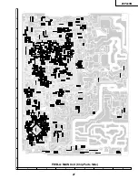
26PL83M
D10
AFC GAIN
02
0-3(00h-03h)
Must be set to "02"
D11
V EHT
07
0-7(00h-07h)
Must be set to "07"
D12
H EHT
03
0-7(00h-07h)
Must be set to "03"
EX1
FAO VOLUME
24
0-50(00h-32h)
Must be set to "24"
EX2
CC-POSITION
21
0-127(00h-7Fh)
EX3
INT
7A
0-255(00h-FFh)
Must be set to "7A"
EX4
A-ATT
5A
0-127
OP1
OPTION1
BA
0-255(00h-FFh)
Must be set to "A4"
OP2
OPTION2
01
0-7(00h-07h)
Must be set to "03"
M01
INPUT LEVEL
09
0-15(00h-0Fh)
Must be set to "09"
M02
MTS VCO
24
0-63(00h-3Fh)
M03
FILTER
1F
0-63(00h-3Fh)
M04
WIDEBAND
18
0-63(00h-3Fh)
M05
SPECTRAL
10
0-63(00h-3Fh)
P01
CONTRAST-PIP
32
0-127(00h-7Fh)
P02
TINT-PIP
29
0-63(00h-3Fh)
Must be set to "29"
P03
COLOR-SAT-PIP
32
0-127(00h-7Fh)
P04
Y-OFFSET-PIP
09
0-31(00h-1Fh)
Must be set to "09"
P05
HXA-PIP
0A
0-255(00h-FFh)
Must be set to "0A"
P06
HADJ-PIP
00
0-15(00h-0Fh)
Must be set to "00"
P07
FREE RUN-PIP
0B
0-15(00h-0Fh)
Must be set to "0B"
P08
TINT-PIP-INPUT
24
0-63(00h-3Fh)
Must be set to "24"
SERVICE
NUMBER
DATA
ADJUSTMENT ITEM
INITIAL VALUE
RANGE
ADJUSTMENT CONTENTS
Table - A
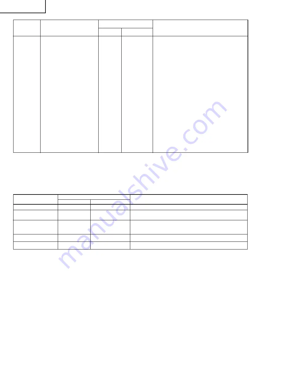
NECESSARY
UNNECESSARY
ADJUSTMENT
PART REPLACED
IC2001
IC201
X
Data is stored in IC2102.
The adjustment is needed to compensate for characteristics of parts
including IC201 and MTS level (M01).
Holding down both the VOL-up and CH-up buttons on the TV set at service mode for more than 2 seconds will
automatically write the above initial values into IC2102.
NOTES
X
IC2102
IC3001
CRT
Holding down both the VOL-up and CH-up buttons on the TV set in
the service mode for more than 2 seconds will automatically write the
above initial values into IC2102. Then perform a complete adjustment.
Adjust items related to picture tube only.
Adjust items related to MTS only (M01~M05).
Table - B
X
X
X
Summary of Contents for 26PL83M
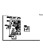
Page 12: ...13 26PL83M 12 12 11 10 9 8 7 6 5 4 3 2 1 A B C D E F G H CHASSIS LAYOUT ...
Page 13: ...14 6 5 4 3 2 1 A B C D E F G H 26PL83M BLOCK DIAGRAM ...
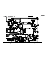
Page 15: ...17 26PL83M 16 12 11 10 9 8 7 6 5 4 3 2 1 A B C D E F G H SCHEMATIC DIAGRAM MAIN 1 Unit ...
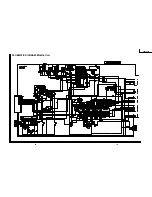
Page 16: ...19 26PL83M 18 12 11 10 9 8 7 6 5 4 3 2 1 A B C D E F G H SCHEMATIC DIAGRAM MAIN 2 Unit ...
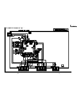
Page 17: ...21 26PL83M 20 12 11 10 9 8 7 6 5 4 3 2 1 A B C D E F G H SCHEMATIC DIAGRAM AV Unit ...
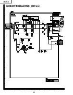
Page 18: ...22 6 5 4 3 2 1 A B C D E F G H 26PL83M SCHEMATIC DIAGRAM CRT Unit ...
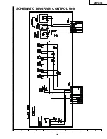
Page 19: ...23 6 5 4 3 2 1 A B C D E F G H 26PL83M SCHEMATIC DIAGRAM CONTROL Unit ...
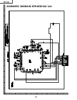
Page 20: ...24 6 5 4 3 2 1 A B C D E F G H 26PL83M SCHEMATIC DIAGRAM MTS MODULE Unit ...
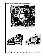
Page 22: ...26 6 5 4 3 2 1 A B C D E F G H 26PL83M PWB A MAIN Unit Wiring Side ...
Page 23: ...27 6 5 4 3 2 1 A B C D E F G H 26PL83M PWB A MAIN Unit Chip Parts Side ...
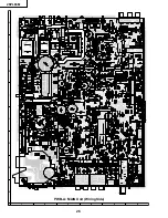
Page 25: ...29 6 5 4 3 2 1 A B C D E F G H 26PL83M PWB F CONTROL Unit Wiring Side ...


