


6
26PL83M
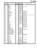
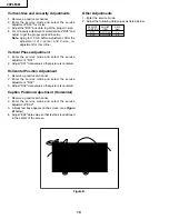
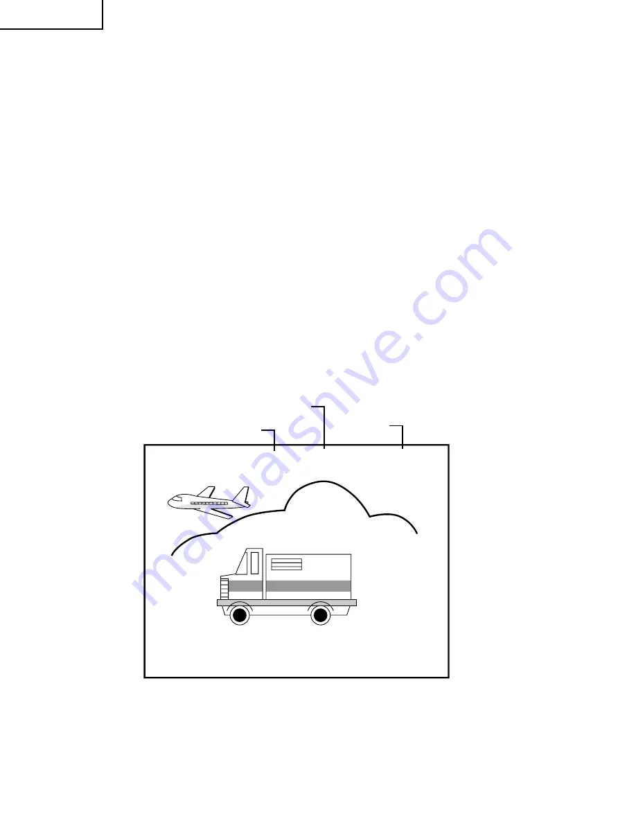
Figure A.
V01
02
CHANNEL
SERVICE ADJUSTMENT NUMBER
DATA NUMBER
For adjustments of this model, the bus data is converted to various analog signals by the D/A converter
circuit.
Note: There are still a few analog adjustments in this series such as focus and master screen voltage.
Follow the steps below whenever the service adjustment is required. See "Table-B" to determine, if serv-
ice adjustments are required.
1. Service mode
Before putting unit into the service mode, check that
customer adjustments are in the normal mode. Use
the reset function in the video adjustment menu to
ensure customer controls are in their proper (reset)
position.
2. Service number selection
Once in the service mode, press the Ch-up or Ch-
down button on the remote controller or at the set.
The service adjustment number will vary in
increments of one, from "V01" to "P08". Select the
item you wish to adjust.
3. Data number selection
Press the Vol-up or Vol-down button to adjust the data
number.
To enter the service mode and exit serv-
ice mode.
To enter the service mode manually just press and hold
the Vol-down and Ch-up buttons at the same time, plug
the AC cord into a wall socket.
Now the TV set is switched on and enters the service
mode.
To exit the service mode, turn the television off by
pressing the power button.
55(085)
Summary of Contents for 26PL83M
Page 12: ...13 26PL83M 12 12 11 10 9 8 7 6 5 4 3 2 1 A B C D E F G H CHASSIS LAYOUT ...
Page 13: ...14 6 5 4 3 2 1 A B C D E F G H 26PL83M BLOCK DIAGRAM ...
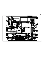
Page 15: ...17 26PL83M 16 12 11 10 9 8 7 6 5 4 3 2 1 A B C D E F G H SCHEMATIC DIAGRAM MAIN 1 Unit ...
Page 16: ...19 26PL83M 18 12 11 10 9 8 7 6 5 4 3 2 1 A B C D E F G H SCHEMATIC DIAGRAM MAIN 2 Unit ...
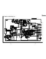
Page 17: ...21 26PL83M 20 12 11 10 9 8 7 6 5 4 3 2 1 A B C D E F G H SCHEMATIC DIAGRAM AV Unit ...
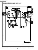
Page 18: ...22 6 5 4 3 2 1 A B C D E F G H 26PL83M SCHEMATIC DIAGRAM CRT Unit ...
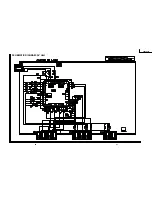
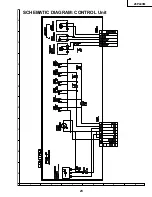
Page 19: ...23 6 5 4 3 2 1 A B C D E F G H 26PL83M SCHEMATIC DIAGRAM CONTROL Unit ...
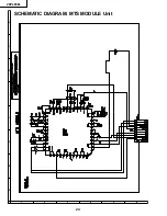
Page 20: ...24 6 5 4 3 2 1 A B C D E F G H 26PL83M SCHEMATIC DIAGRAM MTS MODULE Unit ...
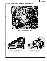
Page 22: ...26 6 5 4 3 2 1 A B C D E F G H 26PL83M PWB A MAIN Unit Wiring Side ...
Page 23: ...27 6 5 4 3 2 1 A B C D E F G H 26PL83M PWB A MAIN Unit Chip Parts Side ...
Page 25: ...29 6 5 4 3 2 1 A B C D E F G H 26PL83M PWB F CONTROL Unit Wiring Side ...


