


25VT-J100
25VT-CJ10
10
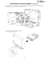
5. Remove the 4 cassette housing control fixing screws, and detach the cassette housing control.
6. Remove the 4 mechanism chassis fixing screws, and detach the mechanism chassis PWB.
7. Remove the 8 main PWB fixing screws, and detach the main PWB.
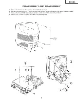
DISASSEMBLY AND REASSEMBLY
(Continued)
Summary of Contents for 25VT-CJ10
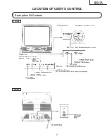
Page 7: ...25VT J100 25VT CJ10 7 LOCATION OF USER S CONTROL Description Of Controls FRONT REAR ...
Page 21: ...25VT J100 25VT CJ10 21 H G F E D C B A 1 2 3 4 5 6 PWB A MAIN UNIT MODEL 25VT J100 ...
Page 22: ...25VT J100 25VT CJ10 22 H G F E D C B A 1 2 3 4 5 6 PWB A MAIN UNIT MODEL 25VT CJ10 ...
Page 29: ...H G F E D C B A 1 2 3 4 5 6 7 8 9 10 11 12 25VT J100 25VT CJ10 25VT J100 25VT CJ10 35 36 ...
Page 31: ...H G F E D C B A 1 2 3 4 5 6 7 8 9 10 11 12 25VT J100 25VT CJ10 25VT J100 25VT CJ10 40 39 ...
Page 55: ...25VT J100 25VT CJ10 71 Memo ...
Page 56: ...25VT J100 25VT CJ10 72 TQ0276 S YO KG Printed in U S A ...