


33
13VT-L200
3. Tape run adjustment
1
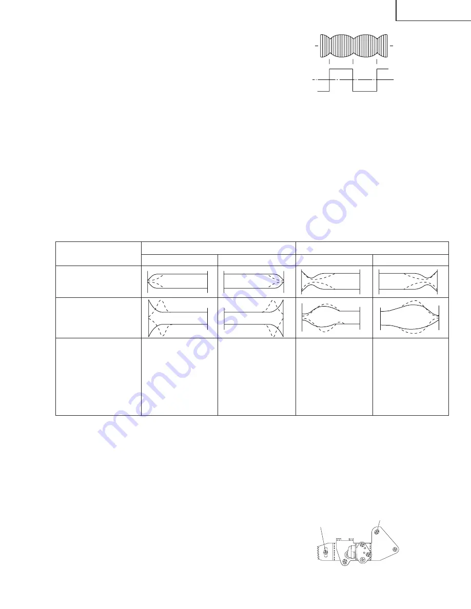
Connect the oscilloscope to PB CHROMA envelope
output test point, set oscilloscope sync to EXT,
trigger-input the PB CHROMA signal (head switch-
ing pulse).
2
Rough adjustment of X value
Tentatively fix A/C head arm screws
1
and
2
by
the method described in Page 30 "Replacement 3".
After shortcircuiting TP7701 and TP7702, plug in the
powercord, then turn on the power. And playback the
alignment tape (VRONBZGS). As a result the auto-
tracking is automatically cancelled, so that the X
value adjustment mode is set.
Move the A/C head with the X value adjustment gear
driver (JiGDRiVER-6) by the method shown in Figure
1-33, and adjust the A/C head so as to get the
maximum envelope waveform. (Note: When the A/C
head is adjusted, adjust so that the maximum en-
velop waveform is obtained nearest the position of
initial setting made in Page 30.)
3
Next, change the alignment tape to VROEFZCS to
play back. Press the tracking button (+), (–) and
change the envelope waveform from max to min and
When the tape is above the helical lead.
When the tape is below the helicallead.
Take-up side
Supply side
Take-up side
Adjustment
Supply side
Supply side guide roller
rotated in clockwise
direction (lowers guide
roller) to flatten
envelope.
Take-up side guide roller
rotated in clockwise
direction (lowers guide
roller) to flatten
envelope.
Supply side guide roller
rotated in counterclock-
wise direction (raises
guide roller) to make the
tape float above the helical
lead. The supply
side guide roller is then
rotated in the clockwise
direction to flatten the
envelope.
Take-up side guide roller
rotated in counterclock-
wise direction (raises
guide roller) to make the
tape float above the
helical lead. The take-up
side guide roller is then
rotated in the clockwise
direction to flatten the
envelope.
Figure 1-35.
4. A/C head X value adjustment
1
Tentatively fix A/C head arm screws
1
and
2
by
the method described in Page 30 "Replacement 3".
2
After shortcircuiting TP7701 and TP7702, plug in the
powercord, then turn on the power. And playback the
alignment tape (VROEFZCS). As a result the auto-
tracking is automatically cancelled, so that the X
value adjustment mode is set.
3
Move the A/C head with the X value adjustment gear
driver by the method shown in Figure 1-33, and
adjust the A/C head so as to get the maximum
envelope waveform. (Note: At this time adjust so as
to get the maximum envelope waveform nearest the
A/C head position which has been set in case of X
value rough adjustment as stated in Page 33, 3-
2
.)
4
Tighten finally the screws
1
and
2
. Be sure to
tighten at first the screw
1
and then the screw
2
.
PB CHROMA
Envelope
Figure 1-34.
Final tightening torque is 0.6N·m (If the screw
2
is
tightened first, the X value may deviate.)
5
Adjust the playback switching point (Refer to the
electric adjustment method.)
6
Playback the self-picture-recorded tape, and check
the flatness of envelope waveform and sound.
Note:
When the A/C head X value adjustment is performed, be
sure to perform at first X value rough adjustment (refer to
Page 33, 3-
2
).
Figure 1-36.
from min to max. At this time adjust the height of
supply and take-up side guide roller with the adjust-
ment driver (JiGDRiVERH-4) so that the envelope
waveform changes nearly parallel.
4
If the tape is lifted or sunk from the helical lead
surface, the PB CHROMA envelope waveform ap-
pears as shown in Figure 1-35.
5
Press the tracking button (+), (–) and make sure that
the envelope waveform changes nearly parallel.
6
Finally check tape crease near the reverse guide. If
tape crease is found, remove it as stated in Page 31
"HEIGHT ADJUSTMENT OF REVERSE GUIDE"
item 3.
1
2
Head switching pulse
CH-1
CH-2
Summary of Contents for 13VT-CL10
Page 7: ...7 13VT L200 Description Of Controls FRONT LOCATION OF USER S CONTROL REAR ...
Page 56: ...56 13VT L200 8 7 10 9 6 5 4 3 2 1 A B C D E F G H CHASSIS LAYOUT PWB B PWB D PWB C ...
Page 57: ...57 13VT L200 17 16 19 18 15 14 13 12 11 10 PWB A ...
Page 58: ...58 13VT L200 8 7 10 9 6 5 4 3 2 1 A B C D E F G H BLOCK DIAGRAM OF TV SECTION ...
Page 59: ...59 13VT L200 17 16 19 18 15 14 13 12 11 10 ...
Page 61: ...61 13VT L200 17 16 19 18 15 14 13 12 11 10 ...
Page 63: ...63 13VT L200 17 16 19 18 15 14 13 12 11 10 ...
Page 67: ...67 13VT L200 17 16 19 18 15 14 13 12 11 10 ...
Page 69: ...69 13VT L200 17 16 19 18 15 14 13 12 11 10 ...
Page 70: ...70 13VT L200 8 7 10 9 6 5 4 3 2 1 A B C D E F G H OVERALL SCHEMATIC DIAGRAM ...
Page 71: ...71 13VT L200 17 16 19 18 15 14 13 12 11 10 ...
Page 74: ...74 13VT L200 8 7 10 9 6 5 4 3 2 1 A B C D E F G H SCHEMATIC DIAGRAM MAIN 1 Unit TV Section ...
Page 75: ...75 13VT L200 17 16 19 18 15 14 13 12 11 10 ...
Page 76: ...76 13VT L200 8 7 10 9 6 5 4 3 2 1 A B C D E F G H SCHEMATIC DIAGRAM MAIN 2 Unit TV Section ...
Page 77: ...77 13VT L200 17 16 19 18 15 14 13 12 11 10 ...
Page 78: ...78 13VT L200 8 7 10 9 6 5 4 3 2 1 A B C D E F G H SCHEMATIC DIAGRAM POWER Unit TV Section ...
Page 79: ...79 13VT L200 17 16 19 18 15 14 13 12 11 10 ...
Page 80: ...80 13VT L200 8 7 10 9 6 5 4 3 2 1 A B C D E F G H SCHEMATIC DIAGRAM MAIN Unit VCR 1 Section ...
Page 81: ...81 13VT L200 17 16 19 18 15 14 13 12 11 10 ...
Page 82: ...82 13VT L200 8 7 10 9 6 5 4 3 2 1 A B C D E F G H SCHEMATIC DIAGRAM MAIN Unit VCR 2 Section ...