


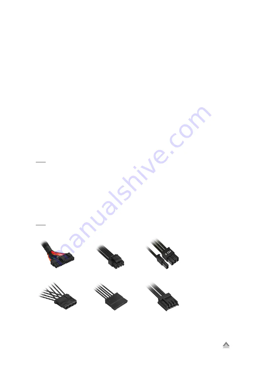
Fig. 4:
4-Pin IDE Connector
Fig. 5:
SATA Connector
Fig. 6:
Floppy Connector
SHP V2
6
5. Installation
If installing into an empty PC case please continue to section 5.1. If a power supply is already installed, remove
it first from the case. To do so, proceed as follows:
1. Turn off your PC. Disconnect the power cord from the wall outlet and your power supply.
2. Open the PC case. For additional information, refer to the PC case’s manual.
3. Disconnect all cables between the power supply and the other PC components (e.g. mainboard, HDDs,
drives, fans, etc.).
4. Remove the mounting screws connecting the power supply to the PC case and then carefully remove the
power supply from the case.
5.1 Installing a Power Supply into a PC Case
1. Insert the power supply into the PC case and place it against the power supply bracket on the rear panel.
For additional information, refer to the PC case’s manual.
2. Attach the power supply from the outside of the case using the provided screws. Ensure that the fan and air
vents of the built-in power supply are not covered.
5.2 Connect the Mainboard and Graphics Card(s)
1. Plug the 20+4-pin mainboard connector (Fig. 1) into the respective port on the mainboard.
2. If your mainboard also features either a 4-pin or 4+4-pin CPU connector, connect the plug with the
mainboard port (Fig. 2).
Note:
The power connection of the mainboard depends on the vendor and may vary. For detailed information on how
to establish the connector, please refer to your mainboard’s manual.
3. If your PCIe graphics card requires an additional power supply, connected the 6-pin or 6+2-pin PCIe
connector to ensure the graphics card receives a stable power supply.
5.3 Connecting Optical Drives and Other Peripheral Devices
1. Connect the 4-pin IDE connector (Fig. 4), SATA connector (Fig. 5) and the 4-pin Floppy connector (Fig. 6)
with the corresponding peripheral devices.
Note:
For additional information, refer to the respective manuals of your drives and peripheral devices.
Fig. 1:
20+4-Pin Mainboard Connector
Fig. 3:
6+2-Pin PCIe Connector
Fig. 2:
4+4-Pin CPU Connector
Summary of Contents for SHP650
Page 1: ...Manual...