


SSG579-585•9.801-193.0•Rev.3/14
13
PRESSURE W
ASHER
OPERA
T
OR’S MANU
AL
MAINTENANCE
Deliming Coils:
Periodic flushing of coils or optional float tank is
recommended.
Step 1 Fill a container with 4 gallons of water, then .
add 1 lb. of deliming powder. Mix thoroughly.
Pour mixture into float tank.
Step 2 Remove wand assembly from spray gun and
put spray gun into float tank. Secure the trig-
ger on the spray gun into the open position.
Step 3 Turn engine on, allowing solution to be
pumped through coils back into the float tank.
The solution should be allowed to circulate 2- 4
hours or until the color changes.
Step 4 After circulating solution, flush the entire
system with fresh water. Clean out float tank
and then reinstall wand assembly to spray gun.
Removal of Soot from Heating Coil:
In the heating process, fuel residue in the form of soot
deposits may develop between the heating coil pipe,
and block air flow which will affect burner combustion.
When soot has been detected on visual observation,
the soot on the coil must be washed off after following
the coil removal steps (See Coil Removal section).
Fuel:
Use clean fuel oil that is not contaminated with water
and debris. Replace fuel filter and drain tank every 100
hours of operation.
Use No.1 or No 2 Heating Oil (ASTM D306) only.
NEVER use gasoline in your burner fuel tank. Gasoline
is more combustible than fuel oil and could result in a
serious explosion. NEVER
use crankcase or waste oil
in your burner. Fuel unit malfunction could result from
contamination.
Fuel Control System:
This machine utilizes a fuel solenoid valve located on
the fuel pump to control the flow of fuel to the combus-
tion chamber. The solenoid, which is normally closed,
is activated by a flow switch when water flows through
it. When the operator releases the trigger on the spray
gun, the flow of water through the flow switch stops,
turning off the electrical current to the fuel solenoid.
The solenoid then closes, shutting off the supply of
fuel to the combustion chamber. Controlling the flow
of fuel in this way gives an instantaneous burn-or-no-
burn situation, thereby eliminating high and low water
temperatures and the combustion smoke normally
associated with machines incorporating a spray gun.
Periodic inspection, to insure that the fuel solenoid
valve functions properly, is recommended. This can
be done by operating the machine and checking to
see that the burner is not firing when the spray gun is
in the OFF position.
Fuel Pressure Adjustment:
To control water temperature, adjust fuel pressure
by turning the regulating pressure adjusting screw
clockwise to increase, counterclockwise to decrease.
NOTE: When changing fuel pump, a bypass plug must
be installed in return port or fuel pump will not prime.
Burner Nozzle:
Keep the tip free of surface deposits by wiping it with
a clean, solvent saturated cloth, being careful not to
plug or enlarge the nozzle. For maximum efficiency,
replace the nozzle each season.
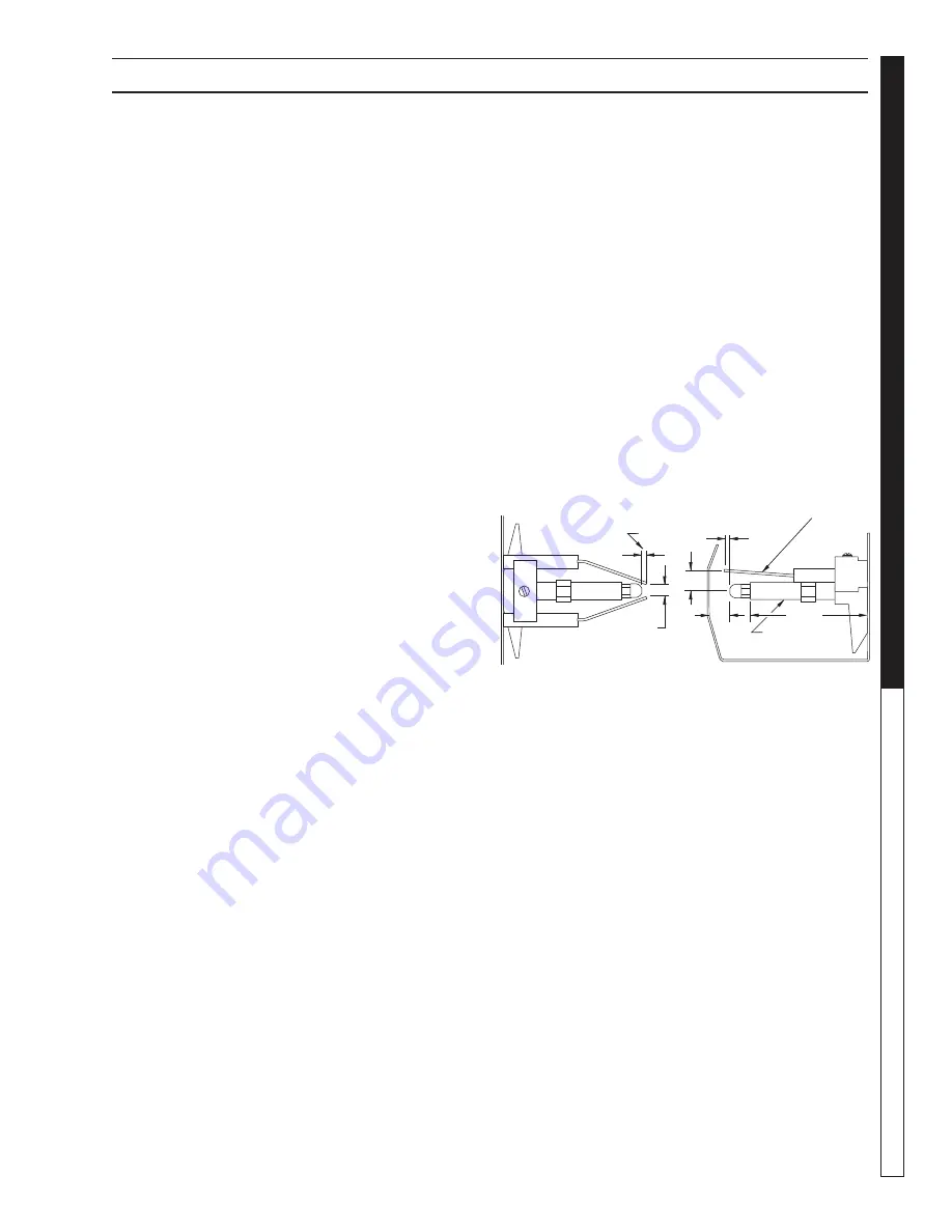
98011930-28
Gap
1/8"
1/8"
3/8"
1/2"
3/16"
Top View
Side View
Nozzle
Adapter
2-7/8"
Periodically Check Wiring Connections. If Necessary
To Adjust Electrodes, Use Diagram.
Electrodes
Electrode Setting: