background image

6

5

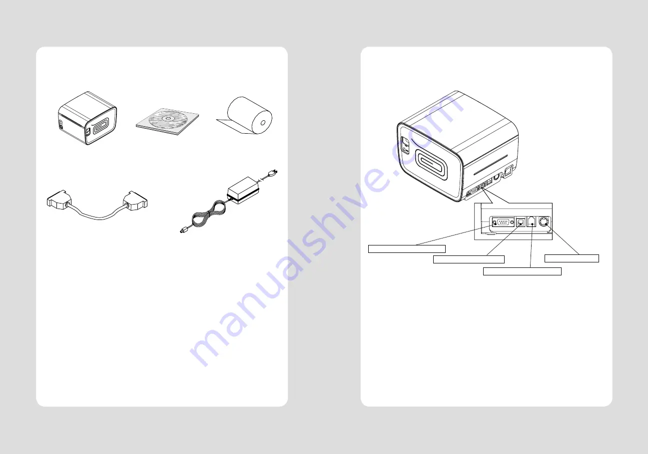
2-2. Connecting the Cables

You can connect up the cables required for printing to the printer. 
They all connect to the connector panel on the back of the printer, which is shown below :

Before connecting any of the cables, make sure that both the printer and the computer are turned off.

For connection to a
host computer.

For connection to a
host computer.

For connection of
the AC adapter.
Never unplug the
AC adapter while 
the printer is on.

Connects to peripheral units
such as cash drawers, etc.
Do not connect this to
a telephone.

INTERFACE CONNECTOR(USB)

PERIPHERAL DRIVE CONNECTOR

POWER CONNECTOR

INTERFACE CONNECTOR(SERIAL)

2-1. Unpacking

Your printer box should include these items. If any items are damaged or missing, please contact your 
dealer for assistance.


The Printer   

                         CD 


            Roll Paper


Interface Cable(optional)                                                        Adaptor(Optional) 


2. Setting Up the Printer

Summary of Contents for SLK-TL100

Page 1: ...ect to change without notice Receipt Printer User s Manual MODEL SLK TL100 TL100 Rev C 01 17 J STEPHEN Lab Ltd 28 6 Gajangsaneopdong ro Osan si Gyeongi do 447 210 Korea TEL 82 31 459 8200 FAX 82 31 45...

Page 2: ...2...

Page 3: ...ications 4 2 Setting up the printer 5 2 1 Unpacking 5 2 2 Connecting the cables 6 2 3 Loading the roll paper 9 3 Control panel and other functions 12 3 1 Control panel 12 3 2 Error Indicating 12 4 Sel...

Page 4: ...nnection to a host computer For connection of the AC adapter Never unplug the AC adapter while the printer is on Connects to peripheral units such as cash drawers etc Do not connect this to a telephon...

Page 5: ...ut 4 24V 5 Drawer kick out drive signal 2 Output 6 Signal GND 2 2 1 Interface Connector Serial Interface PIN SIGNAL I O DESCRIPTION 2 RxD Input Printer transmit data line RS 232C level 3 TxD Output Pr...

Page 6: ...se paper rolls that meet the specifications Do not use paper rolls that have the paper glued to the core because the printer cannot detect the paper end correctly Turn off power switch 1 Make sure tha...

Page 7: ...POWER REMARKS RED RED GREEN Power off OFF OFF OFF Normal power is not supplied to the printer Power on OFF OFF ON Normal power is supplied to the printer On line OFF OFF ON Normal error free mode Cove...

Page 8: ...le time Printing test page constructed with ACII code Set the speed of Serial Interface You can set the BAUDRATE in this mode Printing the HEX value received from the interface Wait for 5 6 seconds if...

Page 9: ...ctricity 4 Take care not to allow the print head to become scratched and or damaged in any way This feature allows experienced users to see exactly what data is coming to the printer This can be usefu...

Page 10: ...ng 2 Print speed 160 mm sec 3 Dot density 180 DPI Hor Ver 180 180 0 141mm 0 141mm dot 4 Printing Width 180 DPI Max 72mm 512 dots 5 Number of print columns No of columns Font A Font B 180 DPI 42 56 6 R...

Page 11: ...here is noise Take the appropriate measure to protect against electrostatic AC line noise etc 9 5 Environmental Requirements 1 Operating Temperature 5 C to 40 C Humidity 10 to 90 RH without condensati...

Page 12: ...aper sensor s to output paper end signals 36 ESC c 4 Select paper sensor s to stop printing 37 ESC c 5 Enable disable panel buttons 38 ESC d Print and feed paper n lines 39 ESC p General pulse 10 Comm...

Reviews: