background image


2 Product description

 │ 

7

kHz

mA


kHz

mA

Fig. 7:  Main view

Left image:  Signal strength in ES1 range (safe-to-touch range)

Right image: Signal strength in ES2 range (

Notice

 symbol)

2.3.3 

Signal behaviour

The generator can optionally be operated with the following sig-

nal behaviour:


Continuous signal


Pulsed signal

with pulsed signal, the signal cycle is 1 : 2 (pulse : pause).

Note:

Operation with pulsed signal extends the operating time of the 

generator compared to operation with continuous signal.

The signal behaviour determines the maximum output power of 

the generator as well as the maximum current in the energized 

pipeline (section 2.3.2).

2.4 

Power supply

The generator is powered by a special, permanently installed Pb 

battery. Information about charging the rechargeable battery can 

be found in section 4.1.

Summary of Contents for FERROPHON FG 150

Page 1: ...01 03 2022 a 108761 en FERROPHON FG 150 generator Operating Instructions ...

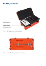
Page 2: ...FG 150 generator Fig 1 FG 150 generator with opened case Control panel Charging socket Cable set port Fig 2 Case with earthing spike view from below ...

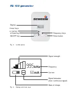
Page 3: ...Fig 4 Display with main view kHz mA Frequency Signal strength Current Fig 3 Control panel Signal behaviour here continuous signal Display ON OFF key Frequency keys Pulse button State of charge Arrow keys Up key Down key ...

Page 4: ... warnings in this document A WARNING Risk of personal injury Could result in serious injury or death A CAUTION Risk of personal injury Could result in injury or pose a risk to health NOTICE Risk of damage to property ...

Page 5: ...ng the frequency 9 3 2 1 Selecting the frequency 9 3 2 2 Activating and deactivating frequencies 9 3 2 3 Adding a frequency 10 3 3 Adjusting the signal strength 11 3 4 Selecting the signal behaviour 12 3 5 Energizing a pipeline directly 12 3 5 1 Connection via conductor loop 12 3 5 2 Connection with earthing spike 13 3 6 Energizing a pipeline indirectly 14 4 Maintenance 16 4 1 Recharging the batte...

Page 6: ...II Contents 5 5 Declaration of conformity 21 5 6 Advice on disposal 22 6 Index 23 ...

Page 7: ...variants Translations Translations are produced to the best of our knowledge The original German version is authoritative Right of reproduction No part of this document may be edited duplicated or circulated in any form without the express consent of Hermann Sewerin GmbH Registered trademarks Registered trademarks are generally not indicated in this docu ment 1 2 Purpose The portable FG 150 genera...

Page 8: ...lations Use the product only as intended Do not make any changes or modifications to the product un less these have been expressly approved by Hermann Sew erin GmbH Only use accessories approved by Hermann Sewerin GmbH Always observe the permitted operating and storage temper atures Handle the product carefully and safely both during transport and when working For example Do not drop the generator...

Page 9: ...y installed in a case Overviews with the names of the generator parts can be found in the front cover fig 1 to fig 3 The scope of delivery of the generator includes FG 150 cable set Extension for cable set Earthing spike As soon as the cable set is connected to the generator the gen erator can energize directly Without the cable set connected the generator energizes indirectly 2 2 Ports The genera...

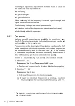
Page 10: ...encies can be deactivated Deactivating can be useful if of all the preset and individual frequencies only certain frequencies are needed for daily work In the main view fig 4 the number of selectable frequencies becomes smaller by deactivation A desired frequency can thus be selected more quickly The list of frequencies fig 1 is always structured as follows 1 Position 1 10 Frequency list 1 and Fre...

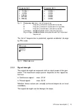
Page 11: ...mage Frequency list 1 with 5 preset frequencies Right image Frequency list 3 with placeholders for 5 individual frequencies The list of frequencies is protected against accidental change by PIN code PIN Code Fig 6 PIN Code view 2 3 2 Signal strength The signal strength corresponds to the output power of the gen erator The maximum output power depends on the signal be haviour Continuous signal max ...

Page 12: ...bars fig 3 left picture the generator operates in the touch safe range ES12 When the Notice symbol appears fig 3 picture on the right the generator operates in the ES2 range3 NOTICE In the ES2 range contact between metal parts e g clamps earthing spike and a body part is painful but is not expected to cause injury Nevertheless the user is responsible for ensuring that persons or animals do not acc...

Page 13: ...signal with pulsed signal the signal cycle is 1 2 pulse pause Note Operation with pulsed signal extends the operating time of the generator compared to operation with continuous signal The signal behaviour determines the maximum output power of the generator as well as the maximum current in the energized pipeline section 2 3 2 2 4 Power supply The generator is powered by a special permanently ins...

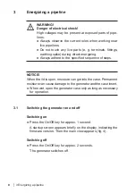
Page 14: ...he specified sequence of steps NOTICE When the lid is open moisture can get into the case Permanent moisture can cause damage to the generator and the case insert When wet open the generator case only as long as necessary for operation 3 1 Switching the generator on and off Switching on Press the On Off key for approx 1 second A startup screen appears briefly on the display indicating the firmware...

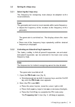
Page 15: ... 2 Activating and deactivating frequencies The factory setting is that all preset frequencies are activated Activated frequencies can be selected in the main view using frequency keys Note The frequencies for indirect energizing cannot be deactivated The generator is switched off 1 Open the PIN Code view fig 6 Simultaneously press both frequency keys and the On Off key until the PIN Code view appe...

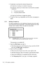
Page 16: ...ncies If individual frequencies have already been created these can also be overwritten Frequency list 3 o 135 Hz Edit 9 o 200 Hz o 200 Hz o 200 Hz o 200 Hz Fig 8 Frequency list 3 view Individual frequencies here top place holder occupied by individual frequency 1359 Hz The generator is switched off 1 Open the PIN Code view fig 6 Simultaneously press both frequency keys and the On Off key until th...

Page 17: ...ress the On Off key to finish entering the frequency The Edit marking disappears 7 Press the pulse key to activate the new frequency 8 Press the Down key repeatedly until the main view appears again 3 3 Adjusting the signal strength The signal strength can be changed in steps The generator is switched on The display shows the main view Press the Up key to increase the signal strength Press the Dow...

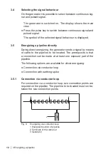
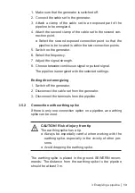
Page 18: ...ng the generator sends a signal by means of cable to the pipeline to be located The prerequisite is that a connection can be made at at least one exposed part of the pipeline The following options are available for direct energizing Connection via conductor loop Connection with earthing spike 3 5 1 Connection via conductor loop For connection via a conductor loop two connection points are required...

Page 19: ...uous signal or pulsed signal The pipeline is energized with the selected settings Ending direct energizing 1 Switch off the generator 2 Disconnect the cable set from the generator 3 Disconnect the terminals from the pipeline 3 5 2 Connection with earthing spike If there is only one connection option on a pipeline an earthing spike can be used A CAUTION Risk of injury from tip The earthing spike ha...

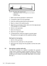
Page 20: ...he generator 7 Select the frequency 8 Adjust the signal strength 9 Choose between continuous signal or pulsed signal The pipeline is energized with the selected settings Ending direct energizing 1 Switch off the generator 2 Disconnect the cable set from the generator 3 Disconnect the clamps from the pipeline and from the earth ing spike 3 6 Energizing a pipeline indirectly If no direct connection ...

Page 21: ...he generator is switched off 1 Place the generator as accurately as possible lengthways over the pipeline to be located 2 Switch on the generator In the main view the Indirect energizing icon appears 3 Select the frequency 4 Adjust the signal strength The pipeline is energized with the selected settings Ending indirect energizing Switch off the generator ...

Page 22: ...is not protected against moisture penetra tion Only charge the battery in dry rooms To charge the battery connect the generator using the AC DC adapter L or vehicle cable L to the power supply 230 V or 12 V The display shows that charging is in progress fig 8 The AC DC adapter and the vehicle cable are available to buy as accessories The battery is protected against overcharging Therefore the gen ...

Page 23: ...stress Always use a clean soft cloth to clean the display surface Never use cleaning agents containing aggressive components e g acidic or abrasive components to clean the display sur face SEWERIN recommends Always remove significant contamina tion immediately If the inside of the case has become wet during use Wipe dry with a cloth Then allow the case to dry in a suitable environment with the lid...

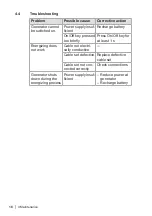
Page 24: ...tery On Off key pressed too briefly Press On Off key for at least 1 s Energizing does not work Cable not electri cally conductive Cable set defective Replace defective cable set Cable set not con nected correctly Check connections Generator shuts down during the energizing process Power supply insuf ficient Reduce power at generator Recharge battery ...

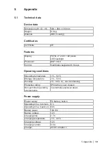
Page 25: ... conditions Operating temperature 15 50 C Storage temperature 15 50 C Humidity 15 90 r h non condensing Protection rating IP54 when cover closed Non permitted operating environments in potentially explosive areas Power supply Power supply Pb battery built in Operating time minimum 2 h Operating time maximum 50 h Battery power 180 Wh Battery voltage 12 V Charging time 7 h Charging temperature 15 40...

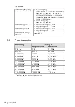
Page 26: ...ith pulsed signal 50 W Transmitting current with continuous signal 0 5 A with pulsed signal 1 A Transmission voltage effective max 120 V 5 2 Preset frequencies Frequency Display in Frequency list Main view 512 Hz 512 Hz 512 Hz 640 Hz 640 Hz 640 Hz 1 100 kHz 1100 Hz 1 10 kHz 8 192 kHz 8192 Hz 8 19 kHz 9 950 kHz 9950 Hz 9 95 kHz 32 768 kHz 32768 Hz 32 8 kHz 41 666 kHz 41666 Hz 41 7 kHz 65 536 kHz 65...

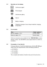
Page 27: ... adapter L12 V LD26 10000 Vehicle cable L12 V ZL05 10200 Other accessories are available for the FERROPHON system Please contact the SEWERIN sales department for further in formation 5 5 Declaration of conformity Hermann Sewerin GmbH hereby declares that the FG 150 gen erator fulfils the requirements of the following guidelines 2011 65 EU 2014 30 EU 2014 35 EU The complete declaration of conformit...

Page 28: ...European Waste Catalogue EWC governs the disposal of devices and accessories in accordance with EU Directive 2014 955 EU Waste EWC code Device 16 02 13 Rechargeable battery 16 06 05 Alternatively devices can be returned to Hermann Sewerin GmbH ...

Page 29: ... Frequency 4 activating 9 adding 10 deactivating 9 list 4 preset 20 selecting 9 I Intended use 1 M Maintenance 17 P Ports 3 Power supply 7 port 3 Purpose 1 R Rechargeable battery charging 16 deep discharge 17 S Safety information 2 Scope of delivery 3 Sendefrequenz siehe Frequenz Settings 3 Signal behaviour 7 setting 12 Signal strength 5 setting 11 switching off 8 switching on 8 Symbols 21 T Troub...

Page 30: ...isenhower Avenida Sur del Aeropuerto de Barajas 28 Planta 2 28042 Madrid España Tel 34 91 74807 57 Fax 34 91 74807 58 www sewerin com info sewerin es Sewerin Portugal Lda Rua Sr Dos Milagres 16 2ºEsq 3800 261 Aveiro Portugal Tlf 351 234 133 740 Fax 351 234 024 446 www sewerin com info sewerin pt Sewerin Sp z o o ul Twórcza 79L 1 03 289 Warszawa Polska Tel 48 22 675 09 69 Tel kom 48 501 879 444 www...

Reviews: