


20
Operating Instructions – MOVIFIT® FDC
3
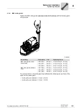
Version for wet areas / corrosion protection (optional)
Unit Structure
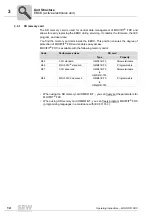
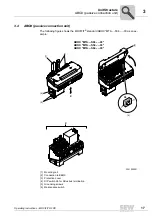
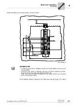
The following figure depicts the additional features of MOVIFIT
®
units in the version for
wet areas:
3041025291
[1] EBOX with special surface treatment (available only in one color)
[2] Signal plug connector
[3] Gasket between ABOX and cover plate
[4] Power plug connector
[5] Screws with thread sealant
[6] Replaceable profile seal
[7] Mounting rail with special surface treatment
[8] ABOX with special surface treatment (available only in one color)
[9] Maintenance switch
[10] Stainless steel screw plugs (optionally available)
[10]
Y
Y
[9]
ABOX "MTA13...-S04.-...-00"
EBOX "
MTC13...-....-00"
DI03
DI01DI02
DI00
DI04DI05
DI06DI07
DI08DI09
DI10DI11
DI12/DO00
DI13/DO01
DI14/DO02
DI15/DO03
ICE Prog PLC
L2
A2
L1
A1
USR
NET
CAN
FDO01
FDO00
FF-ST
ATE
RUN/MS
BF/MS
Eng-E
24V_C
MOVIFIT
®
FDC
X
X
DI03
DI01DI02
DI00
DI04DI05
DI06DI07
DI08DI09
DI10DI11
DI12/DO00
DI13/DO01
DI14/DO02
DI15/DO03
ICE Prog
PLC
L2
A2
L1
A1
USR
NET
CAN
FDO01
FDO00
FF-ST
ATE
RUN/MS
BF/MS
Eng-E
24V_C
MOVIFIT
®
FDC
[1]
[2]
[4]
[6]
[5]
[3]
[7]
[8]
Summary of Contents for MOVIFIT FDC
Page 2: ...SEW EURODRIVE Driving the world...
Page 137: ...Operating Instructions MOVIFIT FDC 137 Index Y Y adapter 77 0 9 24 V terminals connection 55...
Page 138: ......
Page 139: ......