background image

Operating Instructions – MOVITRANS® THM20C / THM20E Pick-Ups 

17

4

Mechanical installation of THM20C

Mechanical Installation

• The space between the THM20C pick-up and the TLS line cable must always be free

of metallic materials.

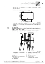
• Observe the following bore dimensions in mm (in):

• Best coupling is achieved when the distance x between the TLS line cable and the

THM20C pick-up is 19 mm (0.75 in). If you change the distance x, the output power
decreases.

The following figure shows a THM20C pick-up installed in an aluminum structure:

2701692427

116 ±0.5

(4.57 ±0.02)

130 ±0.6 (5.12 ±0.02)

THM20C

INFORMATION

For detailed information about the output power in relation to the distance x, refer to
chapter "Technical data of THM20C".

2701748747

x

Distance between TLS line cable and 

THM20C pick-up

[4] TLS10E008-01-1 line cable (supply con-

ductor)

= 19 mm (0.75 in)

[5] TLS10E008-01-1 line cable (return con-

ductor)

[1] Holding plate

[6] TIS profile section system

[2] M6 retaining screw with lock washer for 

securing the screw

[7] Aluminum profile rail

(not included in scope of delivery)

[3] THM20C pick-up

[2]

[1]

[3]

[7]

[6]

[5]

[4]

=

=

X

THM20C

Summary of Contents for MOVITRANS THM20C

Page 1: ...Drive Technology Drive Automation System Integration Services Operating Instructions Mobile Energy Supply MOVITRANS THM20C THM20E Pick Ups Edition 01 2012 19328826 EN ...

Page 2: ...SEW EURODRIVE Driving the world ...

Page 3: ...Storage 8 2 7 Installation 8 2 8 Functional safety technology 8 2 9 Electrical connection 9 2 10 Safe disconnection 9 2 11 Startup operation 10 2 12 Inspection maintenance 10 2 13 Disposal 10 3 Unit Design 11 3 1 THM20C unit design 11 3 2 THM20E unit design 13 4 Mechanical Installation 15 4 1 Mechanical installation of THM20C 15 4 2 Mechanical installation of THM20E 18 5 Electrical Installation 20...

Page 4: ...o property and other notes 1 2 2 Structure of the section related safety notes Section related safety notes do not apply to a specific action but to several actions per taining to one subject The used symbols indicate either a general or a specific hazard This is the formal structure of a section related safety note 1 2 3 Structure of the embedded safety notes Embedded safety notes are directly in...

Page 5: ...xclusion of liability You must comply with the information contained in this documentation to ensure safe operation and to achieve the specified product characteristics and performance features SEW EURODRIVE assumes no liability for injury to persons or damage to equipment or property resulting from non observance of these operating instructions In such cases any liability for defects is excluded ...

Page 6: ...hout authorization improper use as well as incorrect installation or operation may result in severe injuries to persons or damage to property 2 3 Target group Any mechanical work may only be performed by adequately qualified personnel Quali fied personnel in this context are persons who are familiar with the setup mechanical installation troubleshooting and maintenance for the units Further they a...

Page 7: ...ablished that the machine complies with the EMC Directive 2004 108 EC and that the end prod uct categorically conforms to Machinery Directive 2006 42 EC Observe standard EN 60204 1 The rules and regulations of the German employers liability insurance association Berufsgenossenschaft BG in particular BG rules B11 concerning electromagnetic fields must be observed during installation startup and ope...

Page 8: ...that components are not deformed and or insulation spaces are maintained particularly during transportation and handling Electric components must not be mechanically damaged or destroyed Protect the MOVITRANS units from direct sunlight The following applications are prohibited unless explicitly permitted Use in potentially explosive atmospheres Use in areas exposed to harmful oils acids gases vapo...

Page 9: ...information refer to the applicable documentation Protective measures and protection devices must comply with the regulations in force e g EN 60204 1 or EN 61800 5 1 Take suitable steps to ensure that the preventive measures and protection devices described in the operating instructions for the individual MOVITRANS units have been implemented correctly 2 10 Safe disconnection The MOVIPRO drive and...

Page 10: ...ted cables terminals and MOVITRANS units Dangerous volt ages can be present even when the MOVIPRO drive and control unit is disabled and the system is at a standstill The fact that the status LED and other display elements are no longer illuminated does not indicate that the unit has been disconnected from the power supply and no longer carries any voltage Safety functions within the unit may caus...

Page 11: ...Compensation capacity 008 8 nF Inductance 490 4 9 mH Nominal power 008 0 8 kW Type of pick up C U shape Series and generation Type of installation M mobile Component H pick up Type T MOVITRANS Unit Short designation MOVITRANS THM20C008 490 008 1 pick up THM20C pick up Unit 1 THM20C pick up MOVITRANS THM20C008 490 008 1 pick up with PBT housing polybutylene terephthalate With permanently installed ...

Page 12: ...uency U Voltage P Output power I Current T Ambient temperature D 76646 Bruchsal Übertragerkopf MOVITRANS Made in Germany Typ Ser Nr 0053185 Sach Nr Eingang Input THM20C008 490 008 1 13000748 Ausgang Output P I f T U U I f 60 A AC 25 kHz 0 45 C 350 V AC 2 3 A AC 25 kHz 800 W ͺͿ ʹ Ϳ Ͷ ͺͿ ʹ Ϳ Ͷ Betriebsart S1 1530912139 1 U shaped THM20C pick up 2 Permanently installed connection cable including Han ...

Page 13: ...F Inductance 579 5 79 mH Nominal power 020 2 0 kW Type of pick up E flat Series and generation Type of installation M mobile Component H pick up Type T MOVITRANS Unit Short designation MOVITRANS THM20E020 579 007 1 pick up THM20E pick up Unit 1 THM20E pick up MOVITRANS THM20E020 579 007 1 pick up With permanently installed connection cable with flat plug max length 6 m 20 ft depending on order Wit...

Page 14: ...f Frequency U Voltage P Output power I Current T Ambient temperature D 76646 Bruchsal Übertragerkopf MOVITRANS Made in Germany Typ Ser Nr 0053184 Sach Nr Eingang Input THM20E020 579 007 1 13000551 Ausgang Output P I f T U U I f 60 85 A AC 25 kHz 0 40 C 350 V AC 6 A AC 25 kHz 2 kW ͺͿ ʹ Ϳ Ͷ ͺͿ ʹ Ϳ Ͷ Betriebsart S1 2803032203 1 Permanently installed connection cable including Han Q 4 2 connector with...

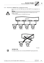
Page 15: ... the cable outputs of the THM20C pick ups connected to the MOVIPRO drive and control unit are always aligned in the same way with the TLS line cable When choosing the mounting position ensure that the cable outputs of the THM20C pick ups do not point in opposite directions up and down They must all either be at the top or at the bottom The following illustration shows correct and incorrect mountin...

Page 16: ...lates made of aluminum Only at tach the holding plates on the back of the THM20C pick up Do not attach the holding plates on the sides Make sure that there is no ferromagnetic or electrically conductive material within a radius of 5 cm 2 in around the TLS line cable INFORMATION The tightening torque for the M6 retaining screws is 3 5 Nm 31 in lb 2701695243 b Distance between TLS line cable and 3 T...

Page 17: ...The following figure shows a THM20C pick up installed in an aluminum structure 2701692427 116 0 5 4 57 0 02 130 0 6 5 12 0 02 THM20C INFORMATION For detailed information about the output power in relation to the distance x refer to chapter Technical data of THM20C 2701748747 x Distance between TLS line cable and THM20C pick up 4 TLS10E008 01 1 line cable supply con ductor 19 mm 0 75 in 5 TLS10E008...

Page 18: ...ithin a radius of 8 to 10 cm 3 to 3 9 in around the TLS line cable The space between the THM20E pick up and the TLS line cables must always be free of metallic materials Observe the following bore dimensions in mm in It is essential that you avoid lateral and angular misalignment of the THM20E as this greatly decreases the transmittable power 2701794827 b Distance between TLS line cable 1 THM20E p...

Page 19: ...exceed 20 mm 0 79 in The following figure shows an installed THM20E pick up INFORMATION For detailed information on the output power refer to chapter Technical data of THM20E 2701790219 x Distance between TLS line cable and 1 THM20E pick up THM20E pick up 2 TLS line cable max 20 mm max 0 79 in 3 E g concrete floor d Distance between the TLS line cables 4 Direction of movement 125 mm 4 92 in d x 1 ...

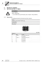
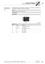
Page 20: ...n WARNING Faulty installation Severe or fatal injuries It is essential to comply with the safety notes in chapter 2 during installation Function Connection of the MOVITRANS THM20C pick up Connection type Han Q 4 2 male Wiring diagram 2444131083 Assignment No Name Function 1 THM pole 1 MOVITRANS pick up pole 1 2 n c Not connected 3 THM pole 2 MOVITRANS pick up pole 2 4 n c Not connected 11 n c Not ...

Page 21: ... pick up to a MOVIPRO drive and application con troller NOTICE Damage to the components when connecting a pick up to a TPM12B mobile converter Damage to property Do not connect the pick up to a TPM12B mobile converter 2704923019 X1021_3 X1021_2 X1021_1 MOVIPRO THM20C THM20C THM20C THM20C X1021_4 TPM12B X21 X31 THM20C THM20C INFORMATION For detailed information refer to the relevant MOVIPRO operati...

Page 22: ...t direc tions Please specify the respective color code for the required cable output direction in the order The following figure shows the different cable output directions Cable code The cable output is on the same side as PIN 1 of the plug insert Black The cable output is on the opposite side of PIN 1 Red 2891993611 PIN 1 PIN 1 BK RD INFORMATION For information about the connection cables refer ...

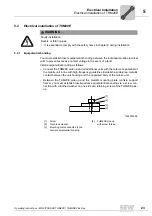
Page 23: ...obile unit in line with high frequency guidelines Establish a wide area metallic contact between the unit housing and the unpainted body of the mobile unit Between the THM20E pick up and the metallic mounting plate vehicle support frame you must establish low impedance equipotential bonding via a screw con nection with a toothed washer on one side at a retaining screw of the THM20E pick up WARNING...

Page 24: ... THM20E connection cable with flat plug INFORMATION For information about the connection cables refer to chapter Technical Data Function Connection of the MOVITRANS THM20E pick up Connection type Flat connector Wiring diagram 2712453771 Assignment No Color cod ing Name Function 1 Black THM pole 1 MOVITRANS pick up pole 1 2 Black THM pole 2 MOVITRANS pick up pole 2 PE Green yellow PE PE connection ...

Page 25: ...connectors of the THM20E con nection cables with angled and straight cable outlet Function Connection of the MOVITRANS THM20E pick up Connection type Han Q 4 2 male Wiring diagram 2444131083 Assignment No Name Function 1 THM pole 1 MOVITRANS pick up pole 1 2 n c Not connected 3 THM pole 2 MOVITRANS pick up pole 2 4 n c Not connected 11 n c Not connected 12 n c Not connected PE PE PE connection 1 1...

Page 26: ... pick up to a MOVIPRO drive and application con troller NOTICE Damage to the components when connecting a pick up to a TPM12B mobile converter Damage to property Do not connect the pick up to a TPM12B mobile converter 2705373579 INFORMATION For detailed information refer to the relevant MOVIPRO operating instructions TPM12B THM20E THM20E X21 X31 THM20E X1011_3 THM20E X1011_2 MOVIPRO THM20E THM20E ...

Page 27: ...t direc tions Please specify the respective color code for the required cable output direction in the order The following figure shows the different cable output directions Cable code The cable output is on the same side as PIN 1 of the plug insert Black The cable output is on the opposite side of PIN 1 Red 2891993611 PIN 1 PIN 1 BK RD INFORMATION For information about the connection cables refer ...

Page 28: ...60 A Working frequency fI 25 kHz Nominal output voltage VO AC 350 V Nominal output current IO AC 2 3 A Nominal output power PN 800 W1 1 Compare section Transmittable power in this chapter Peak output power Pmax 1100 W1 Nominal power loss PL 15 W Inductance 4 9 mH Capacity 8 nF Mechanical data Nominal distance between THM20C and line cable x 19 mm2 0 75 in 2 Compare section Mounting in chapter Mech...

Page 29: ...wer P1 W Nominal power PN W Straight 15 1100 800 Straight 19 1100 800 Straight 24 1100 800 Straight 29 1000 700 Straight 39 700 500 Inner curve with r 750 mm 19 1100 800 Outer curve with r 750 mm 19 1100 800 Vertical curve with α 7 19 1100 800 5048901771 t1 cyclic duration factor for peak power P1 PN Maximum cyclic duration factor for peak power t1 150 s T cycle duration 5048905355 D t T 1 t s P1 ...

Page 30: ...rheating you must determine the peak power P1 as a function of the minimum power P2 and the cycle factor D The following figure shows the permitted peak power ratings P1 5056886155 D P2 W P1 1100 W P1 1050 W P1 1000 W P1 950 W P1 900W P1 850W P1 800 W 0 0 1 0 2 0 3 0 4 0 5 0 6 0 7 0 8 0 9 1 0 100 200 300 400 500 600 700 800 P i f kVA Hz n ...

Page 31: ...C Technical Data 6 1 4 Dimension drawing The following figure shows the dimensions of the THM20C pick up in mm in 58 89 8 0 4 31 5 M6 4x 10⁵ 0 5 116 0 5 130 0 6 130 0 6 186 0 7 29 2 5 12 4 57 4 13 2 3 5 12 7 32 3 54 1 24 112 0 5 4 41 69 0 4 2 7 87 0 4 3 4 1 15 1532406411 P i f kVA Hz n ...

Page 32: ... PN 2000 W1 1 cp section Transmittable mean power of THM20E in this chapter Peak output power Pmax See chapter Transmittable mean power of THM20E Nominal power loss PL 20 W Inductance 5 79 mH Capacity 7 nF Mechanical data Nominal distance between THM20E and line cable x 15 mm2 0 6 in 2 cp section Mounting in chapter Mechanical installation of THM20E Dimensions See dimension drawing page 46 Mass wi...

Page 33: ...is routed in the floor Slight air movement 0 5 ms 1 over the entire surface of the pick up installation correction factor fE2 1 25 Determining the peak power What peak power P1 can you expect with a given continuous power P2 You can determine the temperature rise ϑ compared to the ambient temperature by means of the temperature rise factor k1 and the continuous power P2 of the pick up You can now ...

Page 34: ...l lation condition E1 using the following formula In the case of installation condition 2 you can determine the permitted continuous power P2 using the installation correction factor fE2 Definition of parameters and influencing factors Line cable current IL A Distance between the bottom of the pick up and the top of the line cable x mm Peak power of the pick up P1 W Continuous power of the pick up...

Page 35: ...as a function of the continuous power P2 with the following values Line cable current IL 60 A Ambient temperature ϑ 45 C Installation condition E1 The continuous power of the pick up is calculated using the following formula 2712942475 P1 Peak power of the pick up P2 Continuous power of the pick up P3 Minimal power of the pick up t1 Time here t1 400 s during which the peak power is present at the ...

Page 36: ...ollowing figure shows the peak power P1 as a function of the continuous power P2 with the following values Line cable current IL 75 A Ambient temperature ϑ 45 C Installation condition E1 2713808907 1 x 10 mm 2 x 15 mm 3 x 20 mm P1 W P2 W 1 2 3 1500 2000 2500 3000 3500 4000 650 850 1050 1250 1450 1650 1850 2050 P i f kVA Hz n ...

Page 37: ...owing figure shows the peak power P1 as a function of the continuous power P2 with the following values Line cable current IL 85 A Ambient temperature ϑ 45 C Installation condition E1 2713814539 1 x 10 mm 2 x 15 mm 3 x 20 mm P1 W P2 W 1 2 3 1700 2200 2700 3200 3700 4200 750 950 1150 1350 1550 1750 1950 2150 2350 P i f kVA Hz n ...

Page 38: ...re ϑK of 65 C From this point on the pick up power P4 decreases with increasing pick up temperature ϑK almost linearly with the pick up temperature ϑK The second inflection point of the characteristic curves occurs at the maximum pick up temperature ϑK of 85 C At this temperature the maximum continuous power P2 is reached at the corresponding ambient temperature The temperature rise factor k1 dete...

Page 39: ... Transmittable power at IL 60 A x 20 mm The following figure shows the transmittable power for the following values Line cable current IL 60 A Line cable distance x 20 mm 2714156043 1 ϑ 20 C k1 35 3 2 ϑ 30 C k1 32 4 3 ϑ 45 C k1 35 9 500 1000 1500 2000 2500 3000 0 400 800 1200 1600 2000 2400 2800 3200 1 3 2 P4 W t s 2714687755 1 ϑ 20 C k1 39 5 2 ϑ 30 C k1 36 3 3 ϑ 45 C k1 40 2 500 1000 1500 2000 25...

Page 40: ... at IL 75 A x 10 mm The following figure shows the transmittable power for the following values Line cable current IL 75 A Line cable distance x 10 mm 2714692235 1 ϑ 20 C k1 25 4 2 ϑ 30 C k1 23 3 3 ϑ 45 C k1 25 8 500 1000 1500 2000 2500 3000 3500 4000 0 400 800 1200 1600 2000 2400 2800 3200 1 2 3 P4 W t s P i f kVA Hz n ...

Page 41: ... at IL 75 A x 15 mm The following figure shows the transmittable power for the following values Line cable current IL 75 A Line cable distance x 15 mm 2714700299 1 ϑ 20 C k1 29 2 2 ϑ 30 C k1 26 8 3 ϑ 45 C k1 29 7 500 1000 1500 2000 2500 3000 3500 4000 0 400 800 1200 1600 2000 2400 2800 3200 1 2 3 P4 W t s P i f kVA Hz n ...

Page 42: ...power at IL 75 A x 20 mm The following figure shows the transmittable power for the following values Line cable current IL 75 A Line cable distance x 20 mm 2714708235 1 ϑ 20 C k1 32 5 2 ϑ 30 C k1 29 8 3 ϑ 45 C k1 33 1 500 1000 1500 2000 2500 3000 0 400 800 1200 1600 2000 2400 2800 3200 1 3 2 P4 W t s P i f kVA Hz n ...

Page 43: ...t IL 85 A x 10 mm The following figure shows the transmittable power for the following values Line cable current IL 85 A Line cable distance x 10 mm 2714716683 1 ϑ 20 C k1 22 5 2 ϑ 30 C k1 20 7 3 ϑ 45 C k1 22 9 500 1000 1500 2000 2500 3000 3500 4000 4500 0 400 800 1200 1600 2000 2400 2800 3200 1 2 3 P4 W t s P i f kVA Hz n ...

Page 44: ... at IL 85 A x 15 mm The following figure shows the transmittable power for the following values Line cable current IL 85 A Line cable distance x 15 mm 2714722827 1 ϑ 20 C k1 25 4 2 ϑ 30 C k1 23 3 3 ϑ 45 C k1 22 9 500 1000 1500 2000 2500 3000 3500 4000 0 400 800 1200 1600 2000 2400 2800 3200 1 2 3 P4 W t s P i f kVA Hz n ...

Page 45: ...wer at IL 85 A x 20 mm The following figure shows the transmittable power for the following values Line cable current IL 85 A Line cable distance x 20 mm 2714731915 1 ϑ 20 C k1 28 6 2 ϑ 30 C k1 26 3 3 ϑ 45 C k1 29 1 500 1000 1500 2000 2500 3000 3500 0 400 800 1200 1600 2000 2400 2800 3200 1 3 2 P4 W t s P i f kVA Hz n ...

Page 46: ... THM20E Technical Data 6 2 4 Dimension drawing The following figure shows the dimensions of the THM20E pick up in mm in M6 4x R40 15 0 59 285 0 5 1 2 0 02 305 0 5 12 0 0 02 480 0 8 18 9 0 03 460 0 8 18 1 0 03 30 0 2 2 1 2 0 01 0 08 12 0 47 max 6000 236 2 2712514059 P i f kVA Hz n ...

Page 47: ...9 89 909552 50 sc sued sew eurodrive de West SEW EURODRIVE GmbH Co KG Siemensstraße 1 D 40764 Langenfeld near Düsseldorf Tel 49 2173 8507 30 Fax 49 2173 8507 55 sc west sew eurodrive de Electronics SEW EURODRIVE GmbH Co KG Ernst Blickle Straße 42 D 76646 Bruchsal Tel 49 7251 75 1780 Fax 49 7251 75 1769 sc elektronik sew eurodrive de Drive Service Hotline 24 Hour Service 49 180 5 SEWHELP 49 180 5 7...

Page 48: ...odrive com au Sydney SEW EURODRIVE PTY LTD 9 Sleigh Place Wetherill Park New South Wales 2164 Tel 61 2 9725 9900 Fax 61 2 9725 9905 enquires sew eurodrive com au Austria Assembly Sales Service Wien SEW EURODRIVE Ges m b H Richard Strauss Strasse 24 A 1230 Wien Tel 43 1 617 55 00 0 Fax 43 1 617 55 00 30 http www sew eurodrive at sew sew eurodrive at Belarus Sales Minsk SEW EURODRIVE BY RybalkoStr 2...

Page 49: ...e SEW EURODRIVE CHILE LTDA Las Encinas 1295 Parque Industrial Valle Grande LAMPA RCH Santiago de Chile P O Box Casilla 23 Correo Quilicura Santiago Chile Tel 56 2 75770 00 Fax 56 2 75770 01 http www sew eurodrive cl ventas sew eurodrive cl China Production Assembly Sales Service Tianjin SEW EURODRIVE Tianjin Co Ltd No 46 7th Avenue TEDA Tianjin 300457 Tel 86 22 25322612 Fax 86 22 25323273 info sew...

Page 50: ...rodrive cz sew sew eurodrive cz Denmark Assembly Sales Service Copenhagen SEW EURODRIVEA S Geminivej 28 30 DK 2670 Greve Tel 45 43 9585 00 Fax 45 43 9585 09 http www sew eurodrive dk sew sew eurodrive dk Egypt Sales Service Cairo Copam Egypt for Engineering Agencies 33 EI Hegaz ST Heliopolis Cairo Tel 20 2 22566 299 1 23143088 Fax 20 2 22594 757 http www copam egypt com copam datum com eg Estonia ...

Page 51: ...India Registered Office Assembly Sales Service Vadodara SEW EURODRIVE India Private Limited Plot No 4 GIDC POR Ramangamdi Vadodara 391 243 Gujarat Tel 91 265 3045200 91 265 2831086 Fax 91 265 3045300 91 265 2831087 http www seweurodriveindia com salesvadodara seweurodrivein dia com Assembly Sales Service Chennai SEW EURODRIVE India Private Limited Plot No K3 1 Sipcot Industrial Park Phase II Mamba...

Page 52: ...t Tel 961 1 510 532 Fax 961 1 494 971 ssacar inco com lb Jordan Kuwait Saudi Arabia Syria Beirut Middle East Drives S A L offshore Sin El Fil B P 55 378 Beirut Tel 961 1 494 786 Fax 961 1 494 971 info medrives com http www medrives com Lithuania Sales Alytus UAB Irseva Statybininku 106C LT 63431 Alytus Tel 370 315 79204 Fax 370 315 56175 irmantas irseva lt http www sew eurodrive lt Luxembourg Asse...

Page 53: ...ly Sales Service Moss SEW EURODRIVE A S Solgaard skog 71 N 1599 Moss Tel 47 69 24 10 20 Fax 47 69 24 10 40 http www sew eurodrive no sew sew eurodrive no Pakistan Sales Karachi Industrial Power Drives Al Fatah Chamber A 3 1st Floor Central Com mercial Area Sultan Ahmed Shah Road Block 7 8 Karachi Tel 92 21 452 9369 Fax 92 21 454 7365 seweurodrive cyber net pk Peru Assembly Sales Service Lima SEW D...

Page 54: ...65 68612827 http www sew eurodrive com sg sewsingapore sew eurodrive com Slovakia Sales Bratislava SEW Eurodrive SK s r o Rybničná 40 SK 831 06 Bratislava Tel 421 2 33595 202 Fax 421 2 33595 200 sew sew eurodrive sk http www sew eurodrive sk Žilina SEW Eurodrive SK s r o Industry Park PChZ ulica M R Štefánika 71 SK 010 01 Žilina Tel 421 41 700 2513 Fax 421 41 700 2514 sew sew eurodrive sk Banská B...

Page 55: ...VE KOREA Co Ltd No 1720 11 Songjeong dong Gangseo ku Busan 618 270 Tel 82 51 832 0204 Fax 82 51 832 0230 master sew korea co kr Spain Assembly Sales Service Bilbao SEW EURODRIVE ESPAÑA S L Parque Tecnológico Edificio 302 E 48170 Zamudio Vizcaya Tel 34 94 43184 70 Fax 34 94 43184 71 http www sew eurodrive es sew spain sew eurodrive es Sweden Assembly Sales Service Jönköping SEW EURODRIVE AB Gnejsvä...

Page 56: ...Northeast Region SEW EURODRIVE INC Pureland Ind Complex 2107 High Hill Road P O Box 481 Bridgeport New Jersey 08014 Tel 1 856 467 2277 Fax 1 856 845 3179 csbridgeport seweurodrive com Midwest Region SEW EURODRIVE INC 2001 West Main Street Troy Ohio 45373 Tel 1 937 335 0036 Fax 1 937 332 0038 cstroy seweurodrive com Southwest Region SEW EURODRIVE INC 3950 Platinum Way Dallas Texas 75237 Tel 1 214 3...

Page 57: ... Trading and Engineering Services A75 6B 12 Bach Dang Street Ward 02 Tan Binh District 70000 Ho Chi Minh City Tel 84 8 62969 609 Fax 84 8 62938 842 totien ducvietint com Hanoi Nam Trung Co Ltd R 205B Tung Duc Building 22 Lang ha Street Dong Da District Hanoi City Tel 84 4 37730342 Fax 84 4 37762445 namtrunghn hn vnn vn Vietnam ...

Page 58: ... THM20E 24 Embedded safety notes 4 Equipotential bonding THM20E 23 Exclusion of liability 5 F Functional safety technology 8 I Installation 8 Electrical THM20C 20 Electrical THM20E 23 Mechanical THM20C 15 Mechanical THM20E 18 THM20C 16 THM20E 18 Wiring diagram THM20C 20 Wiring diagram THM20E 24 Installation requirements THM20E 33 M Mechanical installation THM20C 15 THM20E 18 Mounting position THM2...

Page 59: ...C connection cable 28 THM20C dimension drawing 31 THM20C transmittable power 29 THM20E basic unit 32 THM20E connection cable 32 THM20E dimension drawing 46 THM20E transmittable power 33 THM20C Basic unit 28 Bore dimensions 17 Connection cable 28 Dimension drawing 31 Part number 11 Technical data 28 Transmittable power 29 THM20E Basic unit 32 Characteristic curves 38 Connection cable 32 Dimension d...

Page 60: ......

Page 61: ......

Page 62: ......

Page 63: ......

Page 64: ...EURODRIVE Driving the world SEW EURODRIVE Driving the world www sew eurodrive com SEW EURODRIVE GmbH Co KG P O Box 3023 D 76642 Bruchsal Germany Phone 49 7251 75 0 Fax 49 7251 75 1970 sew sew eurodrive com ...

Reviews: