background image

4

Installation

Gear units with solid shafts

20

Operating Instructions – Explosion-Proof VARIMOT

®

 Variable Speed Gear Units and Accessories

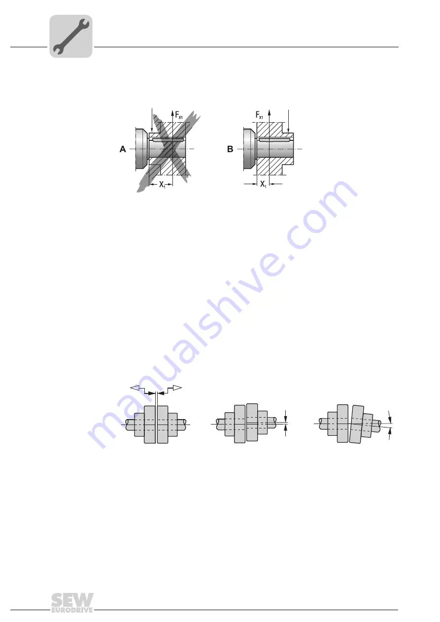
The following illustration shows the correct mounting arrangement (

B

)


of a gear wheel

or chain sprocket for avoiding impermissibly high overhung loads.

• Do not install input and output elements without a mounting device. Use the center

bore with the thread on the shaft end for positioning.

• Power transmission elements should be balanced after fitting and must not give rise

to any excessive radial or axial forces (see the "Geared Motors" catalog for permitted
values).

Mounting 
couplings

Couplings must be mounted and balanced according to the information provided
by the coupling manufacturer:

a) Maximum and minimum clearance
b) Axial offset
c) Angular offset

52021AXX

Fig. 6: Correct mounting arrangement of a gear or sprocket wheel

A

Incorrect

[1]

Hub

B

Correct

[1]

[1]

03356AXX

Fig. 7: Clearance and misalignment for coupling mounting

a)

b)

c)

Summary of Contents for D 16

Page 1: ...Gearmotors Industrial Gear Units Drive Electronics Drive Automation Services Explosion Proof VARIMOT Variable Speed Gear Units and Accessories Operating Instructions Edition 11 2006 11529016 EN...

Page 2: ...SEW EURODRIVE Driving the world...

Page 3: ...inary work 16 4 6 Installation 17 4 7 Gear units with solid shafts 19 5 Startup 21 5 1 Installation and setup of optional equipment 21 6 Inspection and Maintenance 32 6 1 Inspection and maintenance in...

Page 4: ...echnical documentation and the information given on the nameplate It corresponds to valid standards and regulations and meet the requirements of EC Directive 94 9 EC and the EC Directive for Machinery...

Page 5: ...r injury to persons or damage to equipment or property resulting from non observance of these operating instructions In such cases any liability for defects is excluded Product names and trademarks Th...

Page 6: ...t deals with general and operational safety This information is emphasized in particular with the following symbols Electrical hazard Possible consequences Severe or fatal injuries Hazard Possible con...

Page 7: ...egulations in accordance with ElexV 1 or other national regulations must be observed for electrically operated options Technical data and information on approved conditions on site can be found on the...

Page 8: ...Gear Units and Accessories 3 VARIMOT in Explosion Proof Version 3 1 Unit design 52018AXX Fig 1 VARIMOT in explosion proof version 1 Complete output shaft 3 Plate 4 Adjusting plate 5 Housing cover 6 Dr...

Page 9: ...3 2 Unit designation The following diagram shows the type code structure DV 26B WEX II2G eDT 90L 4 TF Temperature sensor Number of motor poles Motor size Motor series Explosion proof version according...

Page 10: ...peed Ma Output torque at minimum and maximum output speed IM Mounting position R Control range ne Input speed Pe Input power kg Weight i Gear ratio Typ Nr na r min Ma Nm IM R ne r min Pe kg 1 kW i Bed...

Page 11: ...Speed Gear Units and Accessories 11 3 4 Overview of mounting options 52019AXX Fig 3 Overview of mounting options 1 Adjustment device with free shaft end NV 2 Adjustment device with handwheel and posi...

Page 12: ...t certificate this indicates the certificate contains special conditions for safe application of the variable gear unit Temperature class VARIMOT variable speed gear units category 2G explosive gas at...

Page 13: ...tmosphere may not exceed 200 C 392 F The system operator must guarantee that a possible accumulation of dust will not exceed a maximum thickness of 5 mm in accordance with EN 50281 1 2 Ambient tempera...

Page 14: ...losion Proof VARIMOT Variable Speed Gear Units and Accessories 51908AXX 51909AXX VARIMOT D16 n 1 min FR N 0 500 1000 1500 2000 2500 300 600 900 1200 1500 1800 DT71D4 DT80K4 DT80N4 FR N VARIMOT D26 n 1...

Page 15: ...Variable Speed Gear Units and Accessories 15 51911AXX 51912AXX FR N VARIMOT D36 n 1 min 0 1000 2000 3000 4000 5000 6000 300 600 900 1200 1500 1800 DV100L4 DV112M4 DV132S4 FR N VARIMOT D46 n 1 min 0 1...

Page 16: ...ave been met Enclosure has been verified 4 5 Preliminary work Variable speed gear units The output shafts and flange surfaces must be thoroughly cleaned of anti corrosion agents contamination or such...

Page 17: ...are replaced by ATEX certified cable glands with strain relief Select the cable gland according to the outer diameter of the cable used All non required cable entries must be sealed with an ATEX cert...

Page 18: ...ents shims spacing rings if necessary Mounting materials for output components Installation tolerances Shaft end Flanges Diameter tolerance in accordance with DIN 748 ISO k6 for solid shafts with d d1...

Page 19: ...Only use ATEX approved input and output components Input and output elements such as belt pulleys couplings etc must have protec tion against contact Never drive belt pulleys couplings pinions etc on...

Page 20: ...e thread on the shaft end for positioning Power transmission elements should be balanced after fitting and must not give rise to any excessive radial or axial forces see the Geared Motors catalog for...

Page 21: ...peed monitoring are possible 1 WEXA Speed monitor incl evaluation electronics with IGEX voltage encoder and digital remote speed indicator 2 WEX Speed monitor incl evaluation electronics with IGEX vol...

Page 22: ...urer Pepperl Fuchs Mannheim Type KFU8 UFC Ex1 D Auxiliary power DC 20 90 V AC 48 253 V ATEX certification number T V 99 ATEX 1471 All installation and setting notes given below refer to the speed moni...

Page 23: ...anufacturer and table 1 The speed monitor must be located outside the potentially explosive atmosphere 60294AXX Fig 8 Connecting the WEXA WEX speed monitor 1 Sensor 14 Startup bypass 3 Sensor 23 DC 24...

Page 24: ...tion continuously red LED PWR green For indicating the supply voltage LED OUT 1 yellow For indicating that relay 1 is active LED OUT 2 yellow For indicating that relay 2 is active LED OUT 3 yellow For...

Page 25: ...Motor frequency Switching speed Switching frequency Pulses per revolution Hz rpm Hz D DF16D DF16B 4 50 300 30 0 6 6 194 19 4 8 150 15 0 4 60 375 37 5 6 240 24 0 8 187 18 7 D DF26D DF26B 4 50 329 32 9...

Page 26: ...attached to the voltage encoder or the connection cable If the switching speed of the variable speed gear unit is less than that in the table see previous page the drive motor must be immediately dis...

Page 27: ...e friction ring carrier Turn the encoder back by one turn and secure with lock nut 2 The switching interval X is now set as follows For VARIMOT D16 26 to 1 mm For VARIMOT D36 46 to 2 mm During operati...

Page 28: ...ees in clockwise direction 3 If a circuit change still does not occur check the voltage supply of the voltage encoder using the evaluation electronics with WEX version Contactless digital remote speed...

Page 29: ...figure 12 Turn input sensitivity potentiometer clockwise until pulse indicator light starts to light up This wiring diagram applies only to digital indicator units type HDA 4110 50 by Dr Horn in comb...

Page 30: ...suring interval quartz adjustment in increments of 0 001 s in the range of 0 010 s to 9 999 s after removing the front panel recommended measuring interval 0 5 to 2 s Pulse multiplier Adjustment in in...

Page 31: ...77VU21WEXA II2G eDT90L4 R107R77VU21WEXA II2G eDT90L4 Data Output speed Pulses revolution Max speed of variable speed gear unit see the table on page 31 na 1 0 6 3 z 2 n 3100 rpm Output speed Pulses re...

Page 32: ...tch to warn that the gear unit is being worked on Use only OEM spare parts from the appropriate and valid spare parts list otherwise the explosion rating of the variable speed drive becomes void Unit...

Page 33: ...Checking torsional play The torsional play of the output shaft is increased through wear of the friction ring The torsional play can be checked as follows 1 Remove fan cover of drive motor 2 Adjust o...

Page 34: ...d Accessories 6 4 Checking the friction ring 52024AXX Fig 14 Checking replacing friction ring 1 Shaft 8 Housing 2 Retaining screws 9 Hollow shaft 7 Needle roller bearing 10 Friction ring 52025AXX Fig...

Page 35: ...ing Precenter via friction ring offset 6 Press hollow shaft and friction ring together using slight pressure if possible use hand lever press until stop is reached 7 Lubricate needle bearing 7 with an...

Page 36: ...If the bearing temperature exceeds 100 C 212 F at one of the test points the respective anti friction bearing must be replaced To ensure safe working conditions and explosion protection it is necessar...

Page 37: ...of VARIMOT Variable Speed Gear Units and Accessories 37 6 7 Completing the inspection maintenance process Ensure that the variable speed drive is assembled correctly and all openings have been plugged...

Page 38: ...ances of the problem Presumed cause Problem Possible cause Solution Drive slips or speed monitoring is triggered Friction ring is worn Replace friction ring see Sec Inspection Maintenance Replacing th...

Page 39: ...urer s documentation Voltage encoder is not suitable for connection to the evaluation electronics IGEX version Replace voltage encoder LED on voltage encoder or speed monitor is not lit or is lit cons...

Page 40: ...auf die sich diese Erkl rung bezieht mit der declares in sole responsibility that the variable speed gear drives in categorie 2G of the VARIMOT 16 46 series that are subject to this declaration are me...

Page 41: ...r Baureihe VARIMOT 16 46 auf die sich diese Erkl rung bezieht mit der declares in sole responsibility that the variable speed gear drives in categories 3G and 3D of the VARIMOT 16 46 series that are s...

Page 42: ...ptional equipment 21 Installation tolerances 18 Installing connecting the IGEX voltage encoder 27 Intended use 4 M Maintenance intervals 32 Malfunction of VARIMOT speed gear units 38 Mounting coupling...

Page 43: ...IVE GmbH Co KG Siemensstra e 1 D 40764 Langenfeld near D sseldorf Tel 49 2173 8507 30 Fax 49 2173 8507 55 sc west sew eurodrive de Drive Service Hotline 24 Hour Service 49 180 5 SEWHELP 49 180 5 73943...

Page 44: ...07251 250 Tel 55 11 6489 9133 Fax 55 11 6480 3328 http www sew com br sew sew com br Additional addresses for service in Brazil provided on request Bulgaria Sales Sofia BEVER DRIVE GmbH Bogdanovetz St...

Page 45: ...Praha Luzna 591 CZ 16000 Praha 6 Vokovice Tel 420 220121234 Fax 420 220121237 http www sew eurodrive cz sew sew eurodrive cz Denmark Assembly Sales Service Kopenhagen SEW EURODRIVEA S Geminivej 28 30...

Page 46: ...te Glasnevin Dublin 11 Tel 353 1 830 6277 Fax 353 1 830 6458 Israel Sales Tel Aviv Liraz Handasa Ltd Ahofer Str 34B 228 58858 Holon Tel 972 3 5599511 Fax 972 3 5599512 lirazhandasa barak online net It...

Page 47: ...urodrive com mx Morocco Sales Casablanca Afit 5 rue Emir Abdelkader MA 20300 Casablanca Tel 212 22618372 Fax 212 22618351 richard miekisiak premium net ma Netherlands Assembly Sales Service Rotterdam...

Page 48: ...1 849 47 70 Fax 221 849 47 71 senemeca sentoo sn Serbia and Montenegro Sales Beograd DIPAR d o o Ustanicka 128a PC Ko um IV floor SCG 11000 Beograd Tel 381 11 347 3244 381 11 288 0393 Fax 381 11 347 1...

Page 49: ...AB Gnejsv gen 6 8 S 55303 J nk ping Box 3100 S 55003 J nk ping Tel 46 36 3442 00 Fax 46 36 3442 80 http www sew eurodrive se info sew eurodrive se Switzerland Assembly Sales Service Basel Alfred lmho...

Page 50: ...Complex 2107 High Hill Road P O Box 481 Bridgeport New Jersey 08014 Tel 1 856 467 2277 Fax 1 856 845 3179 csbridgeport seweurodrive com Dayton SEW EURODRIVE INC 2001 West Main Street Troy Ohio 45373...

Page 51: ...SEW EURODRIVE Driving the world...

Page 52: ...the cost and complexity of daily operations With a global presence that offers responsive and reliable solutions Anywhere With innovative technology that solves tomorrow s problems today With online...

Reviews: