


Installation 9
3.
To install the Direct Motherboard Cable, route the smaller black
connector through one of the available holes, as shown in Figure
8.
Figure 8 – Installing the Direct Motherboard Cable
4.
After carefully pulling the wire through (take caution to not
twist the wire as you pull it and risk damaging the wire on the
metal edges), neatly bend the wire as shown in Figure 9.
Figure 9 – Neatly Installed Direct Motherboard Cable (Top View)
5.
Now that the Direct Motherboard Cable installation is complete,
you may continue installation of the Dell™ PowerEdge™ 750
Adapter on page 10.
10 Installation
Installation
Continue this portion of the installation only after completing
Installation With PCI Slot on page 6, OR Installation Without PCI Slot
on page 8.
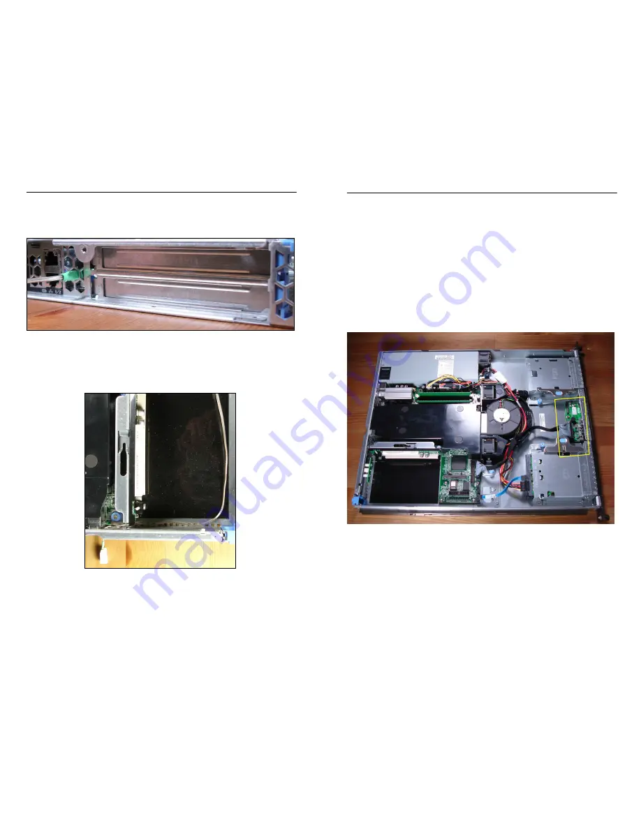
1.
The other end of the Motherboard Cable will be routed through
the server up to the front panel board. Pull sufficient cable
through to reach the front panel board, highlighted in Figure 10.
Figure 10 - Top View of PowerEdge 750 with Front Panel Board Highlighted


