Installation and Service Manual
27
OPERATION
CARBONATION
The purpose of the carbonator is to take water and combine it with CO
2
to create carbonated water. Tap water at street
water pressure (minimum 40 PSI dynamic or flowing pressure in a
1
/
2
" water line) must be forced into a tank that
contains CO
2
(usually at 100 PSI) by using a pump to raise the water pressure above the CO
2
pressure. CO
2
is
absorbed into the water as the water passes through the gas. Cooling and agitating the water will allow it to absorb
more CO
2
gas. Chilling the mixture before dispensing will assist in locking the carbon dioxide into the water. After
dispensing, the CO
2
may be unlocked from the liquid. The CO
2
will gradually leave the liquid due to pressure and
temperature changes.
Components
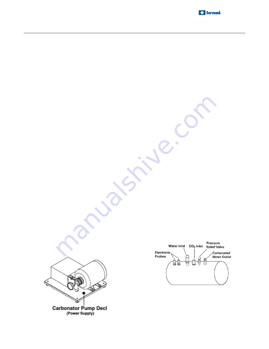
The components of the carbonator are: water pump, an
electric motor to operate the pump, carbonator tank
where the water & CO
2
mix, and a water level control.
Operation
Carbon Dioxide (CO
2
) leaves the storage tank and ar-
rives at the carbonator tank through the gas inlet. Water
supply enters the carbonator pump inlet at regular street
water line pressure (minimum 40 PSI dynamic or flowing
pressure). The water pump increases the pressure of the
water, which allows the water to flow into the carbonator
tank. The CO
2
and the water mix together in the carbon-
ator to produce the carbonated water that is then sent to
the soda dispenser.
The agitation of the water & CO
2
together in the tank un-
der high pressure creates the soda water. The quality of
carbonation (percent of CO
2
mixed in the water) increases
as the water temperature decreases and exposure time
increases.
The water level in the carbonator tank is controlled by a
water level control in the tank. This control turns the pump
motor off and on to maintain a preset level of liquid in the
tank. The water level control may be electronic probes or
a mechanical float.
INTERNAL CARBONATION
The carbonator tank has two inlets and one outlet con-
nection, as well as a relief valve and two conductivity probes.
The water inlet is a double check valve topped with a 3/8"
flared fitting. The carbonator will be pre-plumbed as it leaves
the factory. If the carbonator needs to be serviced or if the
fittings need to be replaced, make sure a nylon washer is
used inside the CO
2
inlet fitting to prevent leaks.
The conductivity probes are used to control the level of
water inside the carbonator tank. The red probe, or the
“high” probe, is the shorter of the two. When the level
of the water reaches the bottom of the red probe, the
pump shuts off. When the water level inside the tank
goes below the bottom tip of the of the black or low
probe. Both probes are wired to the electronic liquid
level control, which is a circuit board mounted inside the
electrical box that activates the pump and motor. Re-
moving the cover of the electrical box will grant access
to the circuit board. As the control receives a signal from
the conductivity probes, it activates the pump motor,
which will pump water into the carbonator until the water
reaches the high probe.
The pump motor and electrical box are mounted together
on a single platform. The pump is a standard 125 GPH
brass rotary vane pump. The flared fittings accept the
same swivel/barb connectors used on the carbonator wa-
ter connections. Also, water enters the pump from the
water source on the side that has the filter.
Notes:
•
Pump Decks for internal carb units must be
within 6 feet of unit.
•
Installation of a carbonator any further away
than the recommended distance is at installer/
owner's risk. Known issues can include, but is
not limited to poor carbonation and/or erratic
carbonation.
Summary of Contents for MD 150
Page 12: ...12 INSTALLATION COLD CARB BAG IN BOX B I B SYSTEM ...
Page 16: ...16 INSTALLATION MD 150 6 VALVE PLUMBING DIAGRAM MD 150 6 VALVE FLEX MANIFOLD ...
Page 18: ...18 INSTALLATION MD 200 250 8 VALVE PLUMBING DIAGRAM MD 200 250 8 VALVE FLEX MANIFOLD ...
Page 42: ...42 EXPLODED VIEWS PARTS DIAGRAMS MD 150 175 200 250 EXPLODED VIEW ...
Page 44: ...44 EXPLODED VIEWS PARTS DIAGRAMS MD 200 250 PARTS LIST ...
Page 45: ...Installation and Service Manual 45 EXPLODED VIEWS PARTS DIAGRAMS MDH 302 402 EXPLODED VIEW ...
Page 46: ...46 EXPLODED VIEWS PARTS DIAGRAMS MDH 302 PARTS LIST MDH 402 PARTS LIST ...
Page 55: ...Installation and Service Manual 55 EXPLODED VIEWS PARTS DIAGRAMS MDH 402 115V WIRING DIAGRAM ...
Page 61: ......


