9.1. REAR-PANEL PORT DESCRIPTIONS
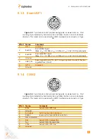
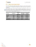
9.1.3 Event/GP1
Figure 9-3:
7-pin female socket pin-numbering guide as viewed end on. Start
counting at pin indicated by bold semi-circle and follow the line in an anti-clockwise
direction. This socket can be paired with a LEMO multipole male connector of type
0B.
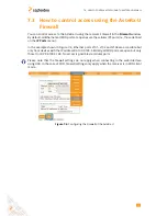
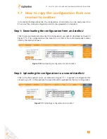
PIN #
Name
Comment
1
GPI 1
reserved
2
Event A
First EVENT input
(Max. V
IL
= 1V, Min. V
IH
= 2V, Max. V
IH
= 24V, 15 K
Ω
pull-down)
3
Event B
Second EVENT input
(Max. V
IL
= 1V, Min. V
IH
= 2V, Max. V
IH
= 24V, 15 K
Ω
pull-down)
4
Ground
5
nRST_IN
Reset signal 3.3V-LVTTL, 5V TTL input. System is reset if the line
is pulled low (<0.6 V)
6
GPI 2
reserved
7
Ground
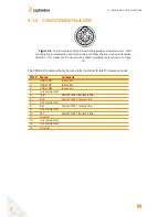
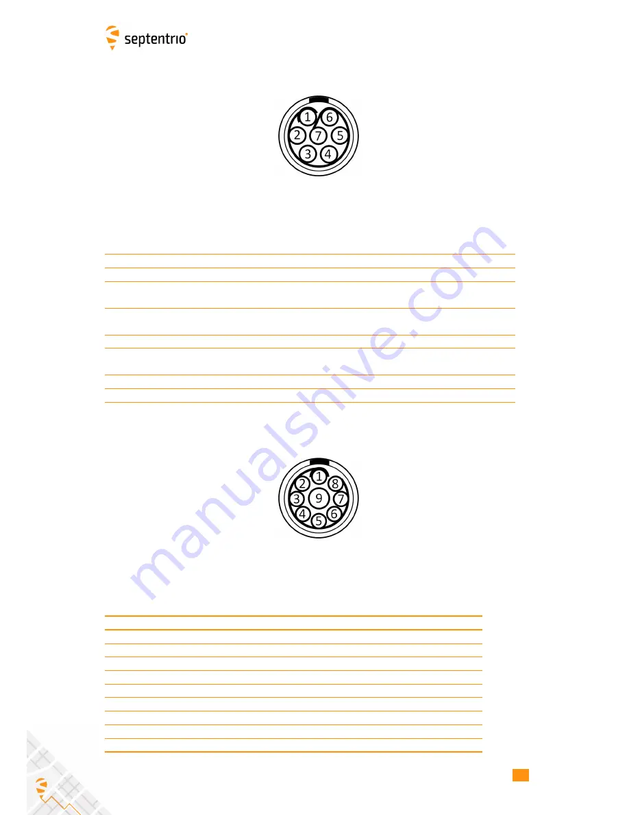
9.1.4 COM2
Figure 9-4:
9-pin female socket pin-numbering guide as viewed end on. Start
counting at pin indicated by bold semi-circle and follow the line in an anti-clockwise
direction. This socket can be paired with a LEMO multipole male connector of type
0B.
PIN #
Name
Comment
1
RTS2
Serial COM 2 RTS line
2
Ground
3
5V output
5V DC output (500 mA max.)
4
RS232
reserved for future RS422 selection
5
Not connected
6
Rx2
Serial COM 2 receive line
7
Tx2
Serial COM 2 transmit line
8
CTS2
Serial COM 2 CTS line
9
Ground
81
Summary of Contents for AsteRx-U
Page 1: ...AsteRx U User Manual ...