


1. Using a #2 Phillips screwdriver,
attach the provided mounting feet to
the four corners of the back of the
unit using the provided screws. (Fig.
9). The feet can be attached either
horizontally or vertically according
to preference.
2. Mark the location on the wall where
you want to mount the unit. If you
mounted the feet horizontally, the
x axis markings should be 17 cm
apart and the y axis markings
should be 7.5 cm apart. If you
mounted the feet vertically, the
x axis markings should be 12.5
cm apart and the y axis markings
should be 12 cm apart.
3. Mount the unit to the wall using the
open side of the mounting feet and
appropriate sized screws.
Wall Mount
Fig. 9: Attach mounting feet
Please Note
:
The FCC etching on the top of the outside enclosure exterior cannot be obstructed from view.
When planning where to mount the Smart Gateway, ensure that the FCC etching is visible and
readable from all perspectives.
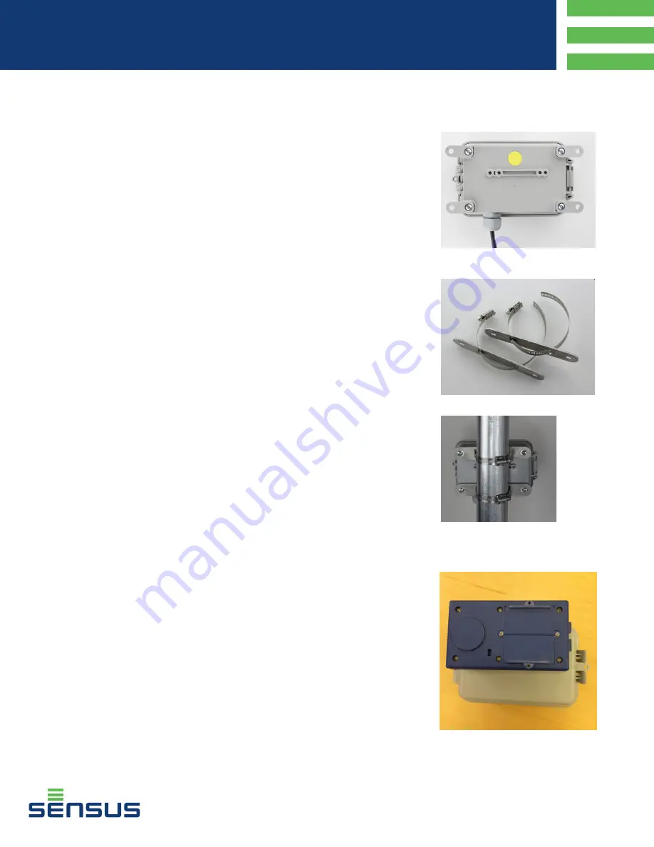
1. Run the customer provided clamps
through the Sensus provided
mounting bars (Fig. 10).
2. Using a #2 Phillips screwdriver,
attach one of the provided mounting
bars, with clamp installed, to the
back of the unit using the provided
screws.
3. Repeat for the second mounting bar
and band/hose clamp.
4. Attach the unit to the pipe using
the band/hose clamps. You can
mount the unit to a horizontal or
vertical pipe (Fig. 11 shows the unit
mounted to a vertical pipe).
Pipe Mount
Fig. 10: Pipe mount bars and clamps
Fig. 11: Attach
to pipe
AIG-10043-03
Smart Gateway
Installation Guide
Recommendation
:
If installing on a pipe, Sensus recommends that you install the transducer cable into the pipe
before wiring it into the Smart Gateway. This will reduce twisting on the transducer cable.
Proper Placement of the CommandLink
For complete instructions on activating the Smart Gateway please refer to the
FieldLogic Smart Gateway Quick Guide.
1. Power on your HHD and the Command Link.
2. Position the CommandLink’s antenna area on the SmartPoint Module’s ASK
location as shown. This location is at the top of the SmartPoint for the Smart
Gateway.
3. Launch FieldLogic Tools.


