


1
3
5
9
4
2
14
11
10
12
13
15
16
11
12
To
body
17
Full Open Capacity
Capacity of the model 121 in the wide-open position can be calculated
using the following formula and K factors:
1.
Q = K P
0
(P
1
- P
0
)
2.
Q = KP
1
2
Q = maximum capacity of the regulator
(in SCFH of 0.6 specific gravity natural gas)
K = the regulator constant
“K” factor;
P
0
=
absolute
inlet pressure (psia)
P
1
=
absolute
outlet pressure (psia)
Use formula 1 when P
1
is less than 1.894
P
0
Use formula 2 when P
1
is greater than 1.894
P
0
3.
K Factors =
1" Pipe Size (outlet)
K= 1400
1-1/4" Pipe Size (outlet)
K = 1750
1-1/2" Pipe Size
K = 2750
2" Pipe Size
K = 4750
2-1/2" Pipe Size
K = 5250
3" Pipe Size
K = 11000
4" Pipe Size
K = 18000
Remember, at the above full open capacities the droop is significantly
greater than specified in the capacity tables. When checking 121
regulator capacity to provide adequate relief valve capacity, use the
above calculated full open capacity.
Installation and Maintenance
Model 121 Regulators – Variations
Maximum Emergency Pressures
The Maximum inlet pressures model 121 bodies may be subjected
to under abnormal conditions without causing internal damage
are as follows:
1" through 2-1/2" pipe sizes
70 psi
3" pipe size
50 psi
4" pipe size
25 psi
The maximum pressures the diaphragms in model 121 regulators may
be subjected to under abnormal conditions without causing internal
damage are as follows:
Model 121-8
set-point plus 5 psi
Model 121-8HP
set-point plus 10 psi
Model 121-12
set-point plus 5 psi
Model 121-16
set-point plus 2 psi
Set-point is defined as the outlet pressure a regulator is adjusted
to deliver.
If any of the above limits are exceeded the regulator must be taken
out of service and inspected. Damaged or otherwise unsatisfactory
parts must be repaired or replaced before returning the regulator
to service.
The maximum pressures that can be safely contained by model 121
diaphragm cases are as follows:
Model 121-8
25 psi
Model 121-8HP
25 psi
Model 121-12
20 psi
Model 121-16
10 psi
Safely contained means no leakage as well as no bursting.
Before using any of the above data, make sure this entire section
is clearly understood.
22
Model 121 Regulators
121-PL (Pressure Loaded)
The 121-PL is a pressure loaded, Pilot Operated Regulator. The
pressure loading of the diaphragm minimizes droop caused by spring
and diaphragm effect, thus providing more accurate control. The
outlet set pressure is controlled by adjusting the pilot regulator of the
121-PL. The main regulator spring is
NOT t
o be adjusted. The two
available pressure ranges are 3-1/2" w.c. to 20 psig and 3-1/2" w.c.
to 35 psig, governed by two available pilot regulators.
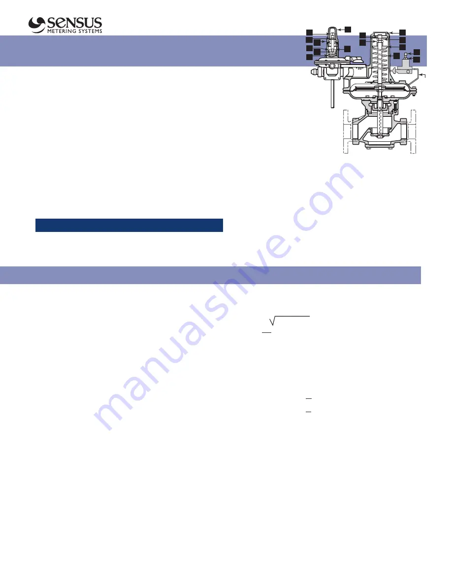
Set-Point Adjustment
The 121-PL is factory adjusted as specified on the order.
To change set point:
1.
Loosen lock nut
12
on pilot regulator top
2.
Rotate set-point adjustment 11 of pilot regulator clockwise to
increase or counter clockwise to decrease the outlet pressure.
3.
When the desired set-point is achieved, retighten lock-nut
12
.
CAUTION
Do not remove main cover cap 1. The upper case is sealed
and pressurized. The main spring is not to be adjusted to control
outlet pressure.
To Service 121-PL
1.
Take regulator out of service
per the following section
“Shut Down”.
2.
Remove cover cap
1
. Measure
depth from top of cover to ferrule
5
for reassembly.
3.
Hold stem
2
from turning using
screwdriver on end of stem.
4.
Unlock nut
3
from nut
4
and remove nut
3
.
5.
Slowly remove nut
4
maintaining pressure on the spring
ferrule
5
to prevent ejection of the spring from the upper case.
CAUTION:
Do not allow stem
2
to unscrew during
removal of nut
4
.
6.
Remove spring
9
.
7.
At pilot, disconnect control line which connects to
downstream piping.
8.
Disconnect pilot supply line between body and pilot regulator.
9.
Follow procedures for standard 121 regulators by size.


