Page 22
UltraWave Product Guide
output alarm signaling). The transmitter unit does not include an input. Refer to
for an
illustration of UltraWave relay output wiring and ground connection details.
illustrates the
input output wiring connection details for both Local control mode and Remote control mode.
T3 - power input
The UltraWave units require 12 to 48 VDC to operate. Pin 1 is negative and pin 2 is positive.
T6 - receiver unit inputs/outputs
T6 connects to output 1, output 2 and an auxiliary (AUX) or self-test input (see
for
connection details). In Local control mode, the two outputs can be configured via the UCM to
report user-specified alarm conditions (see
Alarm data communications on page 11
). A momentary
switch input to the self-test input activates an electronic test of the receiver unit. Self-test activation
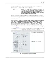
Figure 18 Relay output, power input and ground connection wiring (Rx & Tx)
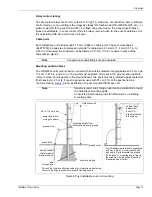
Figure 19 Transmitter/receiver wiring connections
ground connection
machine screw
ground wire
T7 PCB ground
PCB
T3 power input
(12 to 48 VDC)
T6 input/output
connections
ground connection details
(Customer-supplied)
T6
T3
1
2
3
4
5
6
7
8
1
2
NC
COM
NO
NC
COM
NO
-
+
-
+
T6
T3
1
2
3
4
5
6
7
8
1
2
NC
COM
NO
NC
COM
NO
-
+
T6
T3
1
2
3
4
5
6
7
8
1
2
NC
COM
NO
NC
COM
NO
-
+
-
+
power input
(12 to 48 VDC)
AUX input
output 1
output 2
Remote control mode
Receiver unit
Local control mode
Receiver unit
Local control mode
Transmitter unit *
output 1
output 1
output 2
output 2
self-test input
N/A
power input
(12 to 48 VDC)
power input
(12 to 48 VDC)
* The transmitter unit operates in Local control mode only.
In Local control mode the default setting for output 1 is ON = sensor alarm, and for output 2 ON = supervision alarm.
In Local control mode you can use the UCM to specify the conditions which will activate output 1 and output 2.


