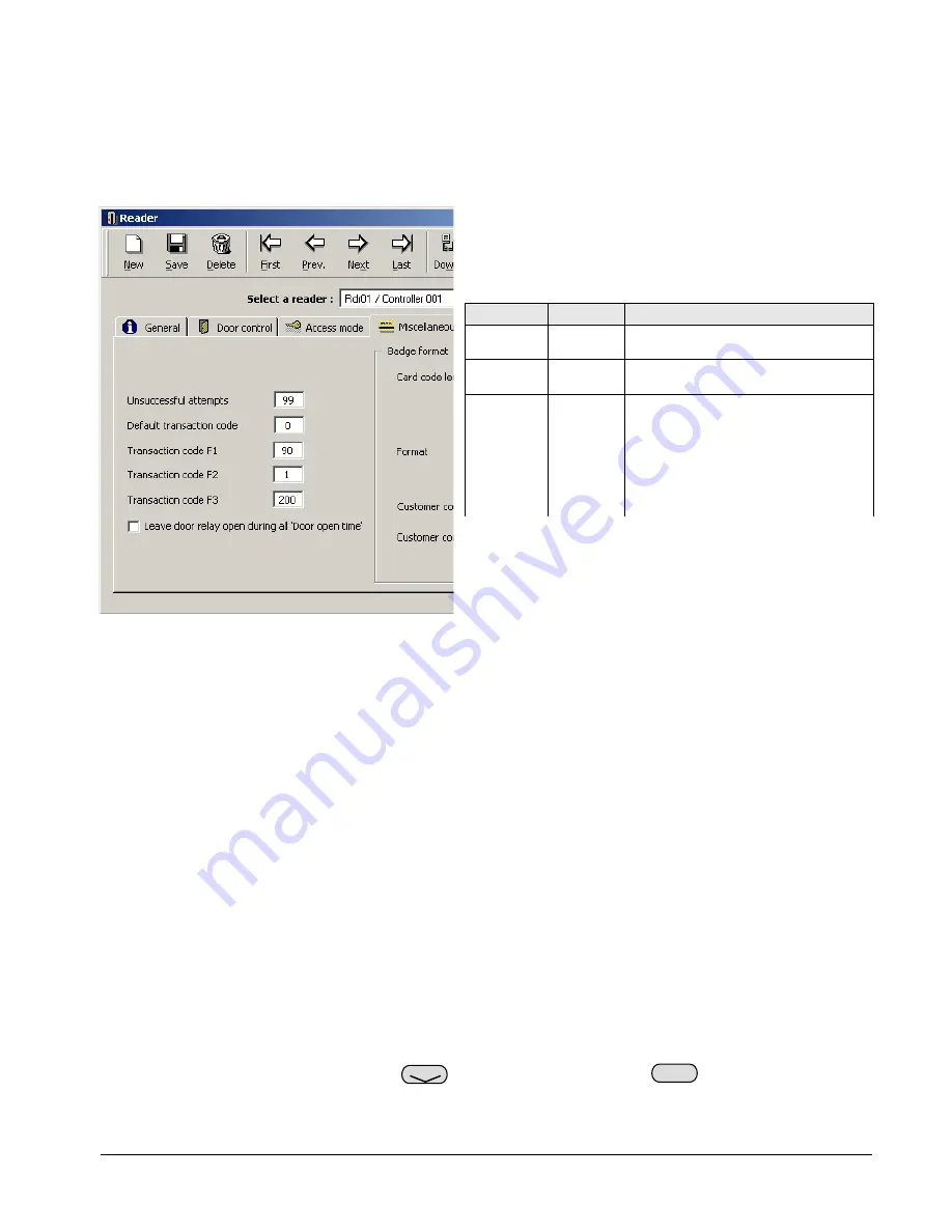
It is now time to integrate the Alarm Keypad with the controller, which is achieved by instructing certain
readers to link to the panel. In our simple example, we are going to link it to Reader 1, which will mean
that, when armed, the door will be locked and ordinary users will not be able to enter. If a Supervisor uses
the door, a timer will commence during which they will be able to disarm the alarm with their PIN code.
Open the reader window by going to
Parameter
,
Controller
, and clicking on the tab
Readers
. You now need
to select the reader in question, and expand it by clicking on its grey ellipse (three dots) button.
Once the reader window has been expanded it is time to
link it to the Alarm Keypad panel. In order to achieve
this, three commands are used and entered into the
Transaction Code boxes F1-F3, as follows:
MNMSC0107_ALARMKEYPAD: Alarm Keypad Installation and User Manual 7/11
Example: Our Alarm Keypad panel is now setup and
configured. In this simple example, it currently has 1
Alarm Zone, which consists of Input 1 and Reader 1. We
also have 1 supervisor who can arm/disarm the system.
Code F#
Example
Notes
4. USING THE SYSTEM.
In this section we will look at using the Alarm Keypad panel. Whilst the panel has a number of control
buttons, there are currently only three distinct functions which can be accessed by authorised users.
Additional functions are due to be introduced in future versions of the software.
Before using the system, it is worthwhile checking that it has set itself up correctly. The LCD panel on the
front of the Alarm Keypad should be showing the current date and time on the top line, and the words
TYPE
YOUR CODE
on the bottom. If it isn’t, try denying power to the unit for a few seconds, then returning it.
4.1 Arming
Perhaps the most important function of the Alarm Keypad is the ability to arm alarms. A supervisor has the
power to arm/disarm any of these Alarm Zones win their PIN, as defined in the
Cardholders
window.
In order to arm an Alarm Zone, you need to enter the following:
PIN code
Alarm Zone
The unit will shown
ARMED
and a long beep is heard. The red
ARM
light on the Alarm Keypad will
begin to flash for the pre-defined delay. Once this delay has elapsed, the red
ARM
light will go solid, and
F1 90
90 is a static command that tells the
software an Alarm Keypad is present.
F2 1
Confirms to which Alarm Zone this
reader belongs, see section 5 for more.
F3 200
The entry/exit delay time given to a
valid supervisor to disarm an active
alarm or exit a door after arming.
This number is always 192 + # where #
is the desired time in seconds.
Thus, the value 200 will give a delay of
8 seconds (192 + 8 = 200).
Arm
Bypass


