ORT/RWT/SGR Series Transducer - CAN Bus Interface (RWT3536IM)
Revision 6, February 2021 - Page 5
Software Implementation
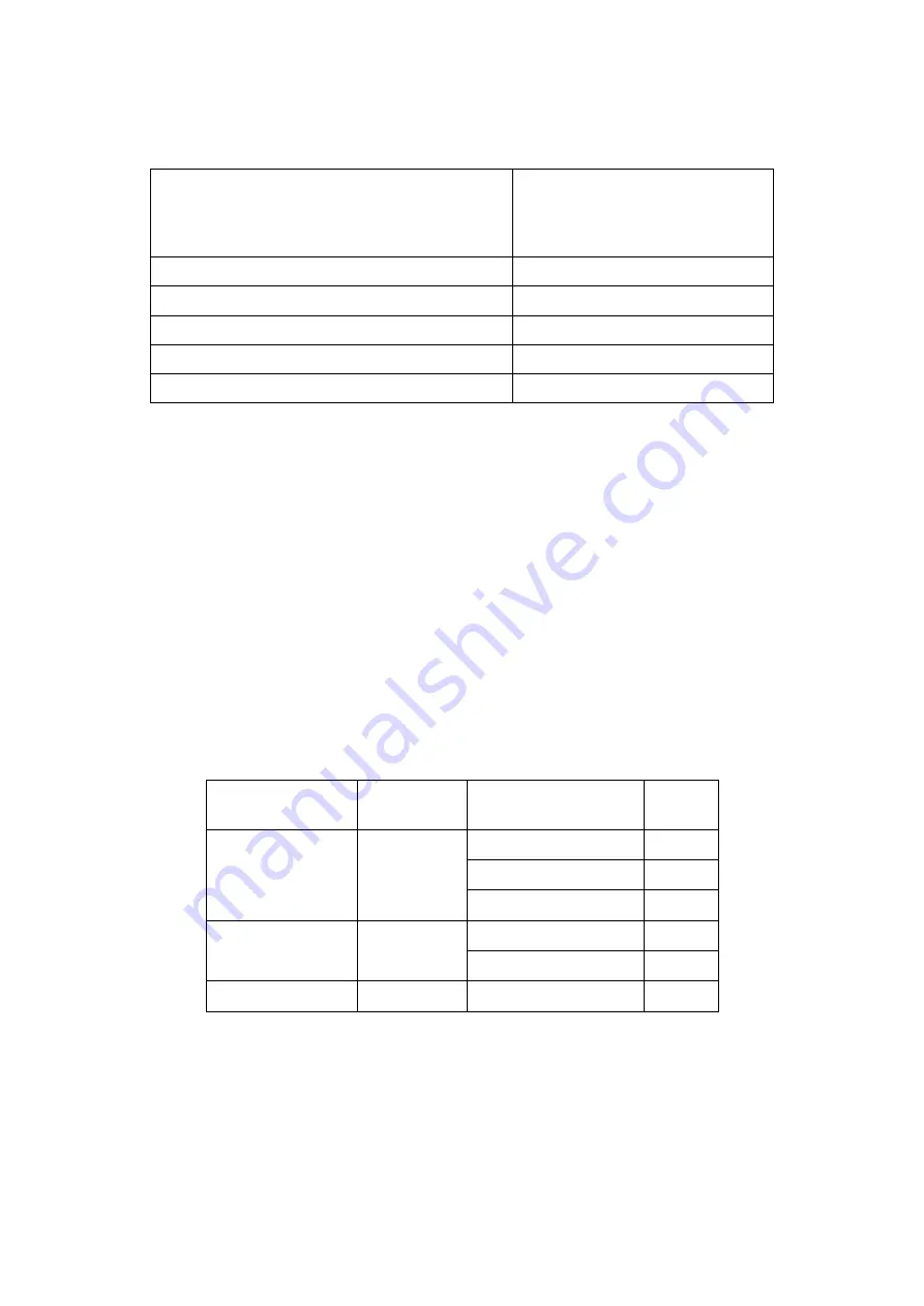
The CAN interface is configured with the settings detailed in Table 1.
Table 1:
Baud rate
Selectable with Transducer Control
1 Mbps
500 Kbps
250 Kbps
100 Kbps
Sample point
75%
Sampling mode
3 samples per bit
Synchronisation jump width (SJW)
2
TSEG1 (PR PHASE_SEG1)
11
TSEG2 (PHASE_SEG2)
4
Transducer data is output on to the CAN bus automatically without application
synchronisation. The output rate can be set by Transducer Control.
The CAN messages output from the transducer use standard 11bit message
identifiers, the identifiers can be set to anything between 1 and 2047, and can be
configured using Transducer Control.
CAN Messages
The data format output in each data frame is configurable by Transducer Control. The
user can output torque in 3 different formats (floating-point, fixed point integer or in
ASCII). Speed can be output as either an integer or ASCII.
The Endianness or byte order for non-ASCII formats can be controlled by Transducer
Control. Table 2 gives an overview of the data and functions available.
Table 2:
The CAN message output rate is either the internal capture rate for the data, or a fixed
rate. If the fixed rate is greater than the internal capture rate, the last captured value
will be repeated. The output rate can be configured using Transducer Control.
Each baud rate carries a maximum output rate, if the capture rate exceeds this, it will
be capped, see the maximums in the CAN Configuration section (Table 5a/5b).
When selecting the output rate, it is important to consider how it may affect the other
devices on the CAN bus, if the rate is too high, then the bus will become congested,
Transducer
Data/Function
Default
Identifier
Data Type
Bytes
Torque
50
IEEE-754 Float
4
Integer (Fixed Point)
4
ASCII
8
Speed
111
Unsigned Integer
4
ASCII
8
Zero Command
156
-
0


