


FA 45 GB - 068-13836 - 12.07.2006_00
Einlegeblatt FA45
Mounting and operating instructions
E 18
Byte
Meaning
Bit pattern
Explaination
n+3
Assessment
Assessment: G, g, B: g = good match with reference
string, G = scan good (without reference string / verify),
B = bad scan.
n+4
Textlength code
X 13 12 11 10 9 8 7
Text length upper 7 bits
n+5
Textlength code
X 6 5 4 3 2 1 0
Text length lower 7 bits
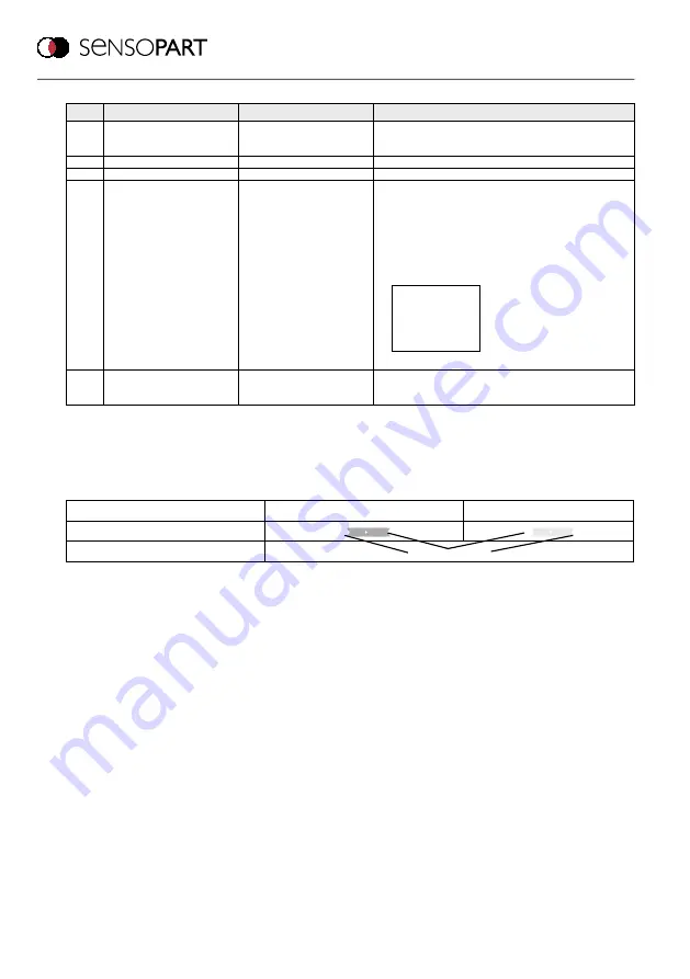
n+6 till
n+21
Position of code in the
picture
Point 1 x upper 7 bits
Point 1 x lower 7 bits
Point 1 y upper 7 bits
Point 1 y lower 7 bits
Point 2 x upper 7 bits
Point 2 x lower 7 bits
Point 2 y upper 7 bits
Point 2 y lower 7 bits
Point 3 x upper 7 bits
Point 3 x lower 7 bits
Point 3 y upper 7 bits
Point 3 y lower 7 bits
Point 4 x upper 7 bits
Point 4 x lower 7 bits
Point 4 y upper 7 bits
Point 4 y lower 7 bits
Arrangement of corner points
n+x
Result string = code content
Content of the read DataMatrix- or Barcode. Length =
number of bytes depending on code content, length =
byte n+4 u. n+5 = “Textlength”
2- Byte values ( e.g. X- or Y- Position, for RS422 and Ethernet)
The X- and Y- coordinates, angles, etc. consist of 2 bytes. The MSB (Most Significant Bit) of all this bytes is
never used (always = 0, to make sure in each case that the Start byte 0xAA is unique with it´s MSB = 1). That
means that only 14 of the 16 bit can be used and the encoding must be like follows.
2-Byte value e.g. X- or Y- Position
Byte 1
Byte 2
Binary content 2 x 8 bit
0 xxx xxxx
0 xxx xxxx
Toatal value binary 2 x 7 bit = 14 bit
xx xxxx xxxx xxxx
Commands to sensor via Ethernet Port 2005: (Generally valid for all sensors)
1. Trigger:
In Run mode, a serial Trigger can be initiated with ASCII “tr” (Important: observe upper and lower case) in
Triggered operating mode.
2. Switch to a new configuration or configuration group:
To switch configuration via RS422 in triggered Run mode, a two byte command is sent from the PLC to the
sensor, which leads to the adjustment of the corresponding configuration. The format of the two byte command
is like follows:
Byte 1: e.g. 0x01 = 0000 0001 = configuration 1; e.g. 0x05 = 0000 0101 = configuration 5, and so on. Byte 2:
complementary content to byte 1, but first bit (MSB) allways „0“
That means with byte 1 = 0x01 = 0000 0001 >> byte 2 = 0111 1110, or with byte 1 = 0x05 = 0000 0101 >> byte
2 = 0111 1010
Note: Block transmission with Ethernet data transfer
With data transfer via Ethernet it can happen that, especailly with bigger data packages (e.g. when much
configurations are used), the total data string is cut in single smaller data packages. This can not be influenced
by the FA45 PC software, as this is controlled from the Ethernet protocoll depending on the load of the Ethernet
connection, and so the exact behavior can not be predicted. This should be considered with long timeout´s in
the software of the date recieving system (PLC or PC).
4
3
1
2