background image

ENGLISH

Pag. 19


³

Once the installation has been completed, verify that each detector reaches at least 
12 Vdc.

3.3  Connection analogue output (only in 12-24 Vdc version)

The default configuration provides a 4-20 mA proportional output. Wiring between the de-

tector and the control panel should be carried out taking into account the following:


³

Use shielded cables. 


³

Wires’ cross section depends on the distance between the control panel and the detec-
tor: for a distance up to m 100 we advise a 3-core wire with cross section area of 0.75 
mm2; for a distance between m 100 and 200 we recommend a 3-core wire with cross 

section of 1.0 mm2; for a distance between m 200 and 300 we recommend a 3-core 

wire with cross section 1.5 mm2.


³

Should any junctions be necessary on wires, please make sure there is no interruption 
on the shield. 


³

Please remember that the shield is to be grounded from the control panel side only. 
Also remember never to connect the shield to the detectors.


³

Ensure the wire connections, either clutching or crimping type, are properly carried 
out with terminals that do not oxidise or loosen. We recommend having them solde-
red.


³

The SMART3-R gas detectors can be connected to control panels available on the mar-
ket having 4-20mA input signals. 

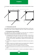
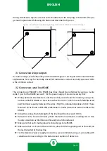
3.4  Remote head connection

The remote head is supplied with the 6-conductor cable already crimped, it must be con-

nected to the base-board of the SMART 3-R detector. Open the detector box by unscrewing 

the 4 screws on the front side and connect the 6-conductor cable to the connector shown in 

Figure 4. Pass the cable through the cable gland in the caseunderside. 

4.  Testing, use and maintenance

4.1  Power ON

When the detector is powered on, the LEDs start blinking yellow during warmup time. After 

one minute, the LEDs remain green during normal status.

Once the warm-up phase is over, the detector can work correctly, although the optimal per-

formances will be achieved after two hours. 

4.2  Testing

Detectors are factory calibrated for the specific gas required by the customers. Future adjust-

ment of the preset calibration can be carried out by employing the calibration keypad. Te-

sting should be carried out by using a gas mixture in the appropriate range, along with our 

Summary of Contents for SMART3-R Series

Page 1: ...Manuale d istruzione Instruction Manual MT4731 rev 3 25 02 2022 2021 SENSITRON S R L All rights reserved www sensitron it Rilevatore per zone non classificate Detector for non classfied areas SMART3 R...

Page 2: ...for any additional information relative to use or repair QUESTO MANUALE DEVE ESSERE LETTO ATTENTAMENTE DATUTTI COLORO CHE HANNO O AVRANNO LA RESPONSABILITA DI INSTALLARE UTILIZZARE O DI PRESTARE UN S...

Page 3: ...ance 20 5 Accessories 21 6 Warranty coupon for repairing 22 7 Instructions for disposal 23 SOMMARIO 1 Introduzione 1 1 1 Descrizione generale 1 1 2 Codici prodotto 2 2 Caratteristiche tecniche 3 2 1 S...

Page 4: ......

Page 5: ...essere richiesta anche la versione 220 Vac Il rilevatore SMART3 R pu montare direttamente un elemento sensibile oppure essere equipaggiato con una testa remota grazie a un cavo a 6 conduttori Il rile...

Page 6: ...O2 OSSIGENO HS ACIDO SOLFIDRICO CL CLORO R410A R410A SD BIOSSIDO DI ZOLFO R407C R407C R407A R407A R407F R407F R404A R404A R1234ZE R1234ZE R134A R134A RIVELATORI LINEA SMART3R s TIPO DI RIVELATORE NOM...

Page 7: ...frarosso Portata contatti rel 1 0 A a 30 Vdc Indicazioni visive 4 LED intelligenti Indicazioni acustiche Buzzer 63 dB a 1 m Materiale custodia Policarbonato Dimensioni custodia Scatola 120 x 120 x 52...

Page 8: ...IUSI SOGLIA 1 SU REL 1 NB REL 1 SEMPRE ASSOCIATO AL FAULT RS485 B RS485 A CONNETTORE TESTA REMOTA PRESENTE SOLO SE SI ACQUISTA LA VERSIONE CON TESTA REMOTA JP13 SENSORE EFFETTO HALL REL 2 REL 1 REL 3...

Page 9: ...in pros simit di emettitori radio ponti radio o apparecchiature simili Si consiglia di installare il rivelatore in zone facilmente accessibili per le operazioni di test e taratura I gas pi leggeri de...

Page 10: ...Il collegamento dei rivelatori alla centrale deve essere realizzato con cavo per con nessioni EIA RS 485 n 2 conduttori con sezione 0 22 0 35 mm2 schermo coppia twistata Capacit nominale tra i condut...

Page 11: ...Assicurarsi che la realizzazione di giunzioni sui cavi di alimentazione mediante dispo sitivi di serraggio o a crimpare sia eseguito a regola d arte con capicorda e o morsetti che nel tempo non si oss...

Page 12: ...izione che ha generato l allarme non si verifica pi 4 4 Manutenzione Sensitron raccomanda un controllo delle perfomance tramite una prova in gas con apposito kit di taratura Se il dispositivo equipagg...

Page 13: ...ura dello Span Reset del dispositivo Impostazione soglie di allarme Impostazione valore di isteresi Modifica del Baud Rate Impostazione dell indirizzo del bus RS485 Visualizzazione della versione del...

Page 14: ...ui prodotti Sensitron valida un anno dalla data di fabbricazione riportata sul prodotto Si intende valida comunque per un anno dalla data di installazione purch la stes sa avvenga entro i dodici mesi...

Page 15: ...ssa in qualsiasi forma o con qualsiasi mezzo inclusi fotocopie registrazioni o altri metodi elettronici o meccanici senza la previa autorizzazione scritta di Sensitron 7 Istruzioni per lo smaltimento...

Page 16: ...ENGLISH Pag 12...

Page 17: ...rd but as optional there s a 230 Vac version SMART3 R gas detector can be equipped directly with a sensing element or with a remote head thanks to a 6 conductors cable The plastic enclosure has two M2...

Page 18: ...URS R152 R152A DIFLUOROETANO ME METHANE R454B R54B BU BUTANE PR PROPANE R1234YF R1234YF R1234ZE R1234ZE R134A R134A R404A R404A ND NITROGEN DIOXIDE HS HYDROGENE SULPHIDE SD SULPHUR DIOXIDE SMART3R ser...

Page 19: ...0 mA at 24 Vdc with infrared sensor Relays contact rating 1 0 A at 30 Vdc Optical indications 4 smart LED Acoustic indications Buzzer 63 dB 1m External case material Polycarbonate External case dimens...

Page 20: ...USED CALIBRATION KEYPAD CONNECTOR B A NA COM NC NA COM NC NA COM NC JP15 JP14 JP24 100 220 Vac AVAILABLE ONLY WITH THE REMOTE HEAD VERSION JP13 HALL EFFECT SENSOR RELAY 2 RELAY 1 RELAY 3 SD1 BUZZER J...

Page 21: ...y radio frequency senders such as radio links or similar Please be also sure that detectors are placed in a convenient location for future main tenance and calibration requirements All of the gases li...

Page 22: ...Wiring between the detectors and the control panel should be made by using con nection cable EIA RS485 2 core wires with section 0 22 0 35 mm2 and shield twisted pair Nominal capacity between the wir...

Page 23: ...or crimping type are properly carried out with terminals that do not oxidise or loosen We recommend having them solde red The SMART3 R gas detectors can be connected to control panels available on th...

Page 24: ...nce through a test gas with the proper calibration kit If the gas detector is equipped with an electrochemical cell or a pellistor sensor the check must be biannual With an infrared sensor the perform...

Page 25: ...reshold settings Hysteresis value setting To reset the device To change or visualize only the Baud Rate To set the address of the RS485 bus To show the firmware version of the detector The OLED versio...

Page 26: ...t As proof will be considered the stamp and date of the installer placed on the present coupon which is to be duly kept by the user and returned to the installer in case of any working tests and repai...

Page 27: ...d to Sensitron Sensitron has a policy of continuous development and improvement of its products As such the specification for the device outlined in this document may be changed without notice In case...

Page 28: ...actdetails SENSITRONs r l Viale della Repubblica 48 20007 Cornaredo MI Italy TEL 39 0293548155 FAX 39 0293548089 www sensitron it E mail sales sensitron it LEADER IN SIL2 SIL3 FIXED GAS DETECTION SYST...

Reviews: