03
02
Multipurpose Wireless Microphone Digital Class-D PA Speaker System
UDR-7F
4
6
7
USR-6F
USR-6FD
4
5
6
7
4
6
7
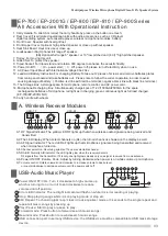
A. Wireless Receiver Modules
A1. RF Signal Indicator: The yellow LED RF lights up that when wireless audio signal are being received and
transmitted.
A2. The LED display: When select channels on (A4), the turned channel is showed on the display as well.
A3. AF Signal Indicator: The red LED AF lights up that microphone signal are being transmitted and received
when microphone turned on.
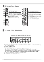
A4.
Channel selector a. Revolving spindle of 16 users selectable channel.
A5.
RA/RB: Diversity A/B indicator; the LED lights glow when the receiver detects
RF signals from the transmitter. If it is only one light glows means only one signal received from one antenna.
A6. Power ON/OFF /Volume Knob: Adjust by turning clockwise when power is on while volume up microphone.
A7.
Volume control: Rotate volume knob clockwise to increase volume to desire level
or counterclockwise to decrease volume until the power switch off.
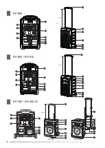
1. Carry Handle: To stretch or retract the carry handle by press up the button one touch.
2. Rear Cover: Fixed related operational units with audio accessories, such as CD player,
digital recording system, auto cassette player, wireless microphone modules, battery.
3. Front Cover: Speaker with fixed grill net.
4. Front Upper Cover: Optional high pitched speaker or close up without speaker.
5. Heat Sink Board: Heat sink use or close up.
6. Loudspeaker: (6A) Optional full range 8" speaker.
(6B)
10" low pitched and
1" high pitched speaker.
7. Trolley: For moving this unit
8. Grilled Net: To protect the speaker
9. Tripod Socket: For tripod stand and rotation 360 degree to enhance the acoustic fidelity.
10. Power On/Off:
「-」
On, power start;
「0」
Off, power off, please turn off electricity when no use.
11. AC Power Input: Meet with international voltage 90v-264v.
12. Lead Acid Battery:Instruction For changing Battery
:
To take out 2 pieces of screws
and
remove
batteries
plates
from
main
panel
board
and
take
batteries
out
.
Please note
to
follow
the
correct
operation in order to avoid
causing damage of battery.
(
Positive-red line with red line terminal
;
negative
-
black
line
with
black
line
terminal
.)
13. The Storage Box: A storage space for microphone, remote control, and AC power cord.
14. Microphone Recharging Box: Simultaneously charge 4pcs of 1.2V/1300mA!2500mA for the spare
rechargeable batteries of microphone, red light as in charging, green continuous light as full load charged.
(EP-700/EP-2001G NO)
15.
Carry handle with wheels
Optional full range 8" speaker, or
(6C)
EP-700 / EP-2001G / EP-800 / EP-810 / EP-900 Series
All Accessories With Operational lnstruction
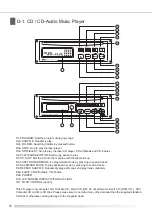
USB-Audio Music Player
1 Power ON/ OFF/ VOL: Turn it clockwise to high volume up
which is turning it on or turn it to anticlockwise to reduce
volume until off position.
2 Error LED indicator: The red light indicator will flash on while it is error reading or playing.
3 Stop: Stop playing songs while it is on playing mode or stop all.
4 EQ/ Repeat: To choosing jazz/ pop/ classic/ rock equalizer mode or 3 seconds to the single repeat and
repeat all music songs by pressing up.
5 Play/ Pause: Start to play or pause to play.
6 Forward mode: Press button to forward search music songs.
7 Rewind mode: Press button to rewind search music songs.
8 USB connection port: Insert any USB device; the USB device must be compatible to USB mass storage
device.
1
2
3
4
5
6
7
8
ON
OFF
Error
Repeat
DIGITAL AUDIO PLAYER
EP-900
55cm(H)
6
3
EP-700 / EP-2001G
55cm(H)
D
12
10
11
AC
V
100-240
OFF ON
/
FOLDER
STOP / EJ
POWER
REP / SHU
disc
EP-800 / EP-810
S
H
U
F
F
L
E
R
E
P
E
A
T
C
D
M
P
3 A
L
L
1 F
O
L
D
E
R
B
A
P
R
O
G
R
A
M
R
E
P
E
A
TA
L
L
1
B
A
D
13
14
10
11
12
D
13
14
10
11
12
S
H
U
F
F
L
E
R
E
P
E
A
T
C
D
M
P
3 A
L
L
1 F
O
L
D
E
R
B
A
P
R
O
G
R
A
M
R
E
P
E
A
TA
L
L
1
B
A
55cm(H)
6
3
6C
6B
EP-700
EP-2001G
6A
3
Summary of Contents for EP-2001G series
Page 2: ......


