Senop HSC-2 User Manual Download Page 16


16 


 25247 


Attaching the HSC-2 to a Drone. 

When using the HSC-2 camera in drones it is always advisable to use professional gimbal, compatible with 

drone. Gimbal insulate drone vibrations and keep camera steady. Use also high-quality drones. 

HSC-2 requirements when used in drone: 


Safe and sturdy installation. The HSC-2 will not survive dropping from heights. 


Power supply. HSC-2 needs power supplied from external source. 

o


Device Voltage supply 7 – 17 VDC 

o


Maximum power consumption 12W, peak 16W 

o


Power consumption is highly depended on the usage of the device. 


Good weather 

o


HSC-2 is a high precision device and not insulated from water 

o


Hyperspectral imaging during rain will not work. 
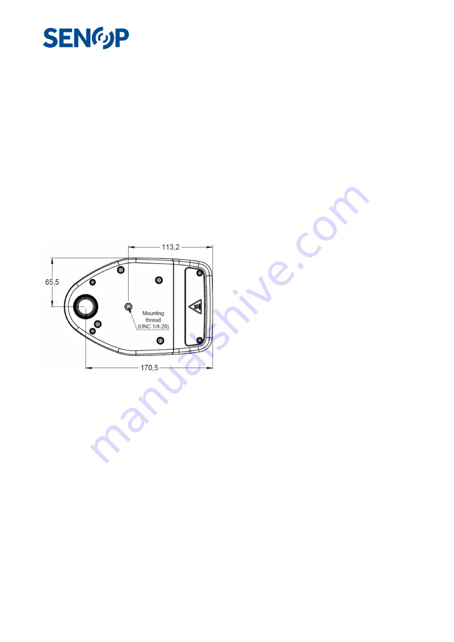
Mechanical fixing 

There  is  a  UNC  ¼-20  mounting  thread  installed  in 

device  aluminum  base  plate.  It  is advisable  to  attach 

baseplate directly against gimbal (metal) fixing plate. 

This also improve cooling for device. Do not cover base 

plate  with  insulating  material,  like  printed  plastic 

plates.  This  may  reduce  device  operation  or  even 

cause thermal shutdown during operation. 

Fixing  may  be  secured  with  for  example  strap  over 

device.  Locate  strap  front side of  display  area. There 

may be other “Upper Mounting Plate” features also in 

gimbal, use those if possible. 

Fixing the cables 

The camera is provided with a protective cover for the connectors. There are 4 distinct parts which can be 

removed for example with plyers, to route the necessary cables through the protective cover. 

Summary of Contents for HSC-2

Page 1: ...Senop Hyperspectral Camera HSC 2 User Guide Version 30 5 4 2019 DRAFT...

Page 2: ...S FOR A PARTICULAR PURPOSE AND NONINFRINGEMENT OR ARISING FROM A COURSE OF DEALING USAGE OR TRADE PRACTICE IN NO EVENT SHALL SENOP OR ITS SUPPLIERS BE LIABLE FOR ANY INDIRECT SPECIAL CONSEQUENTIAL OR...

Page 3: ...ment 8 Open Source Software Notice 8 Specifications 9 Powering 9 Operation conditions 9 Optics 9 Imaging capability 9 Spectral capability 9 Connections 10 Peripherals 10 Device UI 10 Sales Package Con...

Page 4: ...zation 22 Sequence slider 22 Exposure setting Add to Script 22 Script Creator 23 Quick start guide 25 Connecting to the HSC 2 25 Taking a snapshot using the default Sequence 26 Creating and measuring...

Page 5: ...or almost same object or landscape is represented with multiple narrow band wavelengths The Senop Hyperspectral camera can work independently with only power supplied to it with integrated memory or i...

Page 6: ...ol a cross out wheeled waste bin with a bar beneath as below The full text of the EU declaration of conformity is available at the following internet address http senop fi compliance FCC FCC Informati...

Page 7: ...ated or preheated air Keep your device away from radiators and heat sources Keep your equipment away from extremely hot or cold temperatures to ensure that it is used within the specified operating ra...

Page 8: ...ulting from misuse unauthorized modification operation or storage outside the environment specification for the product or in transit damage Open Source Software Notice This product contains Senop HSI...

Page 9: ...ll be inhibited to prevent damages Relative humidity less than 85 not condensing Optics F 3 28 FOV 36 8 deg Focus distance 30cm to limited FOV with less than 30cm distances Imaging capability Image fr...

Page 10: ...S o Internal antenna is located next GPS connector facing up o External antenna not included thru MMCX connector for GPS and Glonass Integrated IMU o Accuracy typically 1 Device UI Display o Resolutio...

Page 11: ...11 25247 o Customized Peli 1400...

Page 12: ...tral Camera is not controlled directly by computer there are certain functions that can be operated from the device own user interface Run script Single shot Settings for o Time and Date o Ethernet o...

Page 13: ...pply 7 17V 20W Ethernet RJ 45 USB C Mini DisplaPort External GPS antenna MMCX AUX connector There are six connectors on the device Ethernet RJ 45 connector Power connector USB connector Display port c...

Page 14: ...ge to the device Recommended Operating Conditions o Supply voltage 1 65V 5 5V o High level input voltage When VccI is 1 65 to 1 95V Min VccI 0 65V When VccI is 2 3 to 2 7V Min 1 7V When VccI is 3 to 3...

Page 15: ...r interface is supplied TRIG pin should be kept all the time in either GND or IO Power voltage 1 65V 6 5V o This can be done for example ON ON type control o TRIG pin is tied to GND with 10k resistor...

Page 16: ...m water o Hyperspectral imaging during rain will not work Mechanical fixing There is a UNC 20 mounting thread installed in device aluminum base plate It is advisable to attach baseplate directly again...

Page 17: ...UX connector USB connector Ethernet or Mini DisplayPort if supported by the drone gimbal Power connector type in cable Barrel Plug 2 5mm I D x 5 5mm O D Positive Center GPS in Drone Use Internal Anten...

Page 18: ...sed to image from a great distance it is useful to consider the affect of the resolution of the image The graph below shows the size what one pixel sees at a given imaging distance For example when th...

Page 19: ...19 25247 0 10 20 30 40 50 60 70 0 10 20 30 40 50 60 70 80 90 100 Size seen by a frame m Imagingdistance m...

Page 20: ...Viewing live image for camera Data browsing Data visualization Sequence editing Script editing Device configuration and updating HSI Data Visualization view In HSI 2 Data Visualization view it is poss...

Page 21: ...pen data o Opens file manager Snapshot o Pause Play Visualization area Live stream False RGB or Grayscale Snapshot still image paused from live stream with defined sequence Saved data opened from file...

Page 22: ...Edit Opens currently selected sequence to the sequence editor for editing sequence Clear all Clears all sequences from the sequence list except default sequence Add to script Lists sequence to the se...

Page 23: ...23 25247 Script Creator...

Page 24: ...nal trigger rising o External trigger decreasing Not supported by the software at the moment o Delay Sequence measure occurrence Number of occurrences or infinite occurrence Sequence interval Interval...

Page 25: ...2 Software On the Device tab press the sign On the opened window Connect the camera to the HSI 2 software Create a Sequence Create a measurement Script Take a Snapshot Record the script with the HSI 2...

Page 26: ...op right corner there is a Visualization window which shows the selected wavelengths for the sequence There is a default sequence shown which has 13 measurement points i e frames between 400 nm 1000 n...

Page 27: ...op right corner of the HSI 2 software To create a new sequence click the button from the Sequence window and select New In the opened window select desired wavelength range number of measurement point...

Page 28: ...s to be measured within the script and the SEQUENCE INTERVAL parameter defines what is the time interval between adjacent measurements Multiple sequences can be added to a script and their order can b...

Page 29: ...e for starting the recording Once the recording is done press OK and back buttons to navigate to the main menu The HSC 2 camera has a Display port which can be used to transfer the video to and extern...

Page 30: ...in HSI 2 software To open the stored data cube press the open icon at the DATA VISUALIZATION sheet Select the desired sequence from the folder and click OK The data cube opens and the spectrum can be...

Page 31: ...es 0 000542 0 000557 These values are used to convert integer values in cube to SI unit different for each image etc Free programs are available to open ENVI files as there is libraries to handle ENVI...

Page 32: ...Acquisition time of the bands compared to the first measurement in nanoseconds senop sensor N A N A N A N A N A Used sensor N A senop frame counter 0 1 3 4 2 Order at which the bands are measured sen...

Page 33: ...e xz package should be extracted first and then the tar package After the extraction connect the HSC 2 camera to the computer using the Ethernet cable and connect the camera to the HSI 2 software From...

Reviews: