Tourguide 2020-D
BedienungsanleitungInstruction manualNotice d‘emploiIstruzioni per l‘usoInstrucciones de manejoGebruiksaanwijzing
Page 1: ...Tourguide 2020 D Bedienungsanleitung Instruction manual Notice d emploi Istruzioni per l uso Instrucciones de manejo Gebruiksaanwijzing...
Page 2: ...99 The functions of the operating controls of the charging case 99 The functions of the operating controls of the charger 100 Putting the components into operation 101 Operation 111 Switching the devi...
Page 3: ...lacement of the obsolete outlet 10 Protect the power cord from being walked on or pinched particularly at plugs convenience receptacles and the point where it exits from the appa ratus 11 Only use att...
Page 4: ...having the same character istics as the original part Unauthorized substitutions may result in fire electric shock or other hazards Safety check Upon completion of any service or repairs to this devi...
Page 5: ...rposes It is considered improper use when the product is used for any application not named in the corresponding instruction manual Sennheiser does not accept liability for damage arising from imprope...
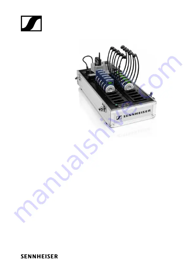
Page 6: ...ur Sennheiser partner EZL 2020 20 L charging case including instruction manual of the overall system L 2021 40 charger SK 2020 D bodypack transmitter SKM 2020 D radio microphone HDE 2020 D II stethose...
Page 7: ...rophones with special connecting cable e 825 S e 835 e 845 In addition you can connect any audio source e g a flash MP3 player to the bodypack transmitter SKM 2020 D radio microphone This extremely ru...
Page 8: ...reliability since temperature and voltage of the accupacks are monitored during charging Long accupack service life due to overcharge protection and recovery of deep discharged accupacks Safe storage...
Page 9: ...compartment cover 5 BA 2015 accupack 6 ON OFF button 7 Red LED LOW BATT MUTE 8 Yellow LED PEAK 9 rocker button 10 SET button 11 Battery compartment 12 Antenna 13 Charging contacts 14 Battery compartm...
Page 10: ...ctive cap for operating controls shown removed the follow ing operating controls become acces sible in turn by turning the protective cap 7 SET button 8 button 9 button 10 Operation battery status ind...
Page 11: ...0 D II stethoset receiver 6 1 3 5 6 4 2 1 Earbows 2 Red green LED for charge status 3 LC display 4 Volume control 5 Channel selection button 6 Charging contacts 1 Channel display 2 4 step battery stat...
Page 12: ...eceiver 6 1 3 4 5 2 6 1 Volume control 2 Channel selection button 3 LC display 4 LED for charge status 5 ON OFF button 6 Headphone socket 1 Channel display 2 4 step battery status display 3 Volume dis...
Page 13: ...ypack transmitter 2 Red LED CHARGE ERROR 3 Green LED READY 4 Storage place for radio micro phone 5 19 charging compartments for receivers slaves light blue in the diagram 6 LED POWER 7 LED TEMP ERROR...
Page 14: ...slave charging compart ments light blue in the diagram 2 Master charging compartment with channel copy function 3 Green LED COPY AVAILABLE 4 COPY button 5 Yellow LED SELECT 6 Red LED POWER 7 Mains sw...
Page 15: ...el provides information on the remaining battery BA 2015 accupack capacity 3 segments capacity approx 100 2 segments capacity approx 70 1 segments capacity approx 30 Battery icon flashing LOW BATT LIN...
Page 16: ...ing deactivating the lock mode on page 131 LINE CH 03 MIC Display backlighting After pressing a button the display remains backlit for approx 30 seconds Display of the energy saving mode When there is...
Page 17: ...The radio microphone is switched on and the capacity of the batteries BA 2015 accupack is sufficient Red LED flashing The batteries are the BA 2015 accupack is going flat LOW BATT In addition the 4 s...
Page 18: ...io microphone as described on page 43 see Adjusting the radio microphone s input sensitivity on page 128 MUTE display When the radio microphone is muted MUTE 5 appears on the display see Muting the ra...
Page 19: ...waves No RF signal is being received on the selected channel or the received signal level is too low No tower no radio waves HDE 2020 D II only The receiver is in standby mode You can however change t...
Page 20: ...ge LED lights up yellow orange The built in rechargeable battery is defective Please contact your Sennheiser partner Volume display The volume display 3 provides information on the current volume leve...
Page 21: ...until the temperature drops to a safe level All charging processes are interrupted until the temperature drops to a safe level LED indication for automatic copying function The LED COPY AVAILABLE 8 l...
Page 22: ...itter 1 as an LED CHARGE ERROR 2 and an LED READY 3 which indicate the following operat ing states No LED lit The charging compartment for accupack bodypack transmitter 1 is ready for operation but em...
Page 23: ...D SELECT 5 Meaning flashes yellow You have just switched on the device LED flashes for a maximum of 2 seconds or an error has occurred lights up yellow The charger is connected to a PC and the Confere...
Page 24: ...ng compartment 2 or you place a receiver into the master charging compartment 2 or you switch on a receiver that is already placed into the master charging compartment 2 and at least one receiver is p...
Page 25: ...turns to the se lection mode without storing the chang es made ESC function SET button Standard display Changes to the selection mode Selection mode Changes to the setting mode of the selected menu Se...
Page 26: ...bows apart Switches the stethoset receiver on EK 2020 D II Operating control Function 2 1 5 Volume control 1 Turning the volume control Changes the volume Channel selection button 2 Changes to the nex...
Page 27: ...20 D The operating controls The functions of the operating controls of the charger 4 7 Operating control Function COPY button 4 Starts the channel copy function see page 123 Mains switch 7 Switches th...
Page 28: ...and open the battery com partment cover 4 Insert the BA 2015 accupack 5 or the batteries as shown in the diagram on the left Please observe correct polarity when inserting the accupack bat teries Clo...
Page 29: ...1 of the bodypack transmitter 1 Lock the plug by screwing down the coupling ring Switch the line input on as described on page 126 Adjust the sensitivity of the line input as described on page 127 Sig...
Page 30: ...ning it counterclockwise 4 2 Slide back the display section 4 as far as it will go 4 Open the battery compartment cover 13 13 Insert the batteries or the BA 2015 accupack as shown on the battery compa...
Page 31: ...ight During charging do not put the case cover on the charging case 12 11 11 11 The charging case has four plastic feet to ensure that it cannot slip on the sur face on which it is placed CAUTION RISK...
Page 32: ...m the mains To connect the charging case to the mains Connect the mains cable to the mains socket 12 see Setting up the charging case on page 104 Plug the mains connector into a wall socket To disconn...
Page 33: ...hen using the Conference Control software it automatically sorts all char ger displays according to ascending serial numbers The assignment of the charger displays of the software to the chargers beco...
Page 34: ...provide additional ventilation Make sure the mechanical loading of the rack is even to avoid a hazardous condition When connecting the device to the power supply observe the information indicated on t...
Page 35: ...108 Tourguide 2020 D Putting the components into operation 438 258 10 3 7 2 156 7 399 120 6 101 7 70 12 3 482 6 465 1 69 7 120 6 38 7 30 50...
Page 36: ...idual PC or integrated into an existing net work The charger cannot communicate with several PCs at the same time The charger also functions without connection to a PC Connecting the network cable Use...
Page 37: ...3 pin IEC mains connector to ensure a reliable mains ground connection of the charger especially when you are using an extension cable or a multi outlet power strip Avoid circuit overloading If necess...
Page 38: ...ypack transmitter on Briefly press the ON OFF button 6 The display 15 indicates the device name and then switches to the standard display To switch the bodypack transmitter off Press and hold the ON O...
Page 39: ...iver automatically switches on when you pull the earbows 1 apart The display 3 switches on 1 3 When you release the earbows the receiver switches to standby mode audio deactivated and then switches of...
Page 40: ...or switch off the transmitter the receiver automatically switches off after 5 minutes 3 6 5 Switching the charging case on off To switch the charging case on Set the main switch 13 to position I The L...
Page 41: ...eries of the receiv ers in the charger are recharged The Conference Control software detects the charger in the network To switch the charger off Set the mains switch 7 to position 0 The red LED POWER...
Page 42: ...earing defects Adjust the volume to a low level before using the receiver 6 Use the volume control 4 of the HDE 2020 D II or the volume control 1 of the EK 2020 D II to adjust the volume so that you c...
Page 43: ...the charging compart ment for accupack bodypack transmitter 1 When placed into a charging compartment the bodypack transmitter au tomatically switches off The red LED CHARGE ERROR 2 of the charging c...
Page 44: ...he charging process may take longer if the accupack is deep discharged and first has to be reconditioned by a deep discharge recovery charge the ambient temperature is close to or over 40 C since in o...
Page 45: ...y take longer if the rechargeable battery is deep discharged and first has to be recondi tioned by a deep discharge recovery charge the temperature of the built in rechargeable battery is over 40 C or...
Page 46: ...echargeable batteries of the HDE 2020 D II and EK 2020 D II receivers For more information on the HDE 2020 D II and EK 2020 D II receivers with their built in Lithium Polymer rechargeable batteries re...
Page 47: ...ectly into the charging compartment Charging time of a completely discharged rechargeable battery at room tem perature Receiver Charging time HDE 2020 D II approx 2 5 hours EK 2020 D II approx 5 hours...
Page 48: ...he bodypack transmitter or the radio microphone to the desired channel use the operating menu of the device An overview of the operating menus is given from page 134 onwards Make sure that the lock mo...
Page 49: ...OFF button until the standard display is shown Setting the channel on the receiver In order for the receiver to receive the signal from the bodypack transmitter or radio microphone it has to be set to...
Page 50: ...ver whose channel you want to copy Place this receiver into the charging compartment with channel copy func tion master 10 2 The LED COPY AVAILABLE 8 3 lights up green as long as the channel copy func...
Page 51: ...ppening you have to set the systems to different channels a system con sists of one bodypack transmitter or one radio microphone and any number of receivers Configuring L 2021 40 via a PC The Conferen...
Page 52: ...When the track has finished the guide can un mute the microphone and continue talking To deactivate the muting function Slide the MUTE switch 2 back to the right The red LED LOW BATT MUTE 7 goes off...
Page 53: ...ce you then have to switch on the line input as follows Press the SET button 10 The operating menu appears and the first menu item CHAN flashes on the display Repeatedly press the rocker button 9 in t...
Page 54: ...ivity so that the LINE level display 5 shows full deflection during the loudest passages but the yellow LED PEAK 8 does not light up permanently Press the SET button 10 to permanently store the settin...
Page 55: ...deflection If on the other had the input sensitivity is adjusted too low the transmission link will be undermodulated which would result in a signal with high back ground noise The input sensitivity i...
Page 56: ...er Radio microphone To display the transmission frequency assigned to the current channel Press the SET button The operating menu appears and the first menu item CHAN flashes on the display Repeatedly...
Page 57: ...hes on the display Repeatedly press until RESET flashes on the display Press the SET button RST OK flashes on the display Press the SET button to load the factory preset default settings DONE briefly...
Page 58: ...s on the display Press the SET button LOC OFF flashes on the display Press LOC ON flashes on the display Press the SET button to activate the lock mode STORED briefly appears on the display indicating...
Page 59: ...SET MUTE LOW BATT Bodypack transmitter Radio microphone To display the version number of the operating system installed Press the SET button The operating menu appears and the first menu item CHAN fla...
Page 60: ...ge 126 SENSIT LINE Changes the sensitivity of the line input see page 127 SENSIT MIC Changes the sensitivity of the microphone input see page 127 FREQ Displays the frequency of the current channel see...
Page 61: ...3 sec OFF ON Stores settings Current setting LINE LIN OFF LIN ON Switching the line input on off SET SET 0 24 Stores settings Current sensitivity setting SENSIT 24 dB 06 dB Adjusting the sensitivity o...
Page 62: ...F LOC ON LOCK Activating deactivating the lock mode Current setting Current setting SET LOC ON V 1 001 LOCKED SERVIC Displaying the version number Exiting the operating menu Current version number Dea...
Page 63: ...Setting mode Selecting the channel Current channel CHAN CH 01 CH 04 01 06 Stores settings CH 01 SET SET SET 3 sec EXIT RESET 0 36 Stores settings Current sensitivity setting SENSIT 36 dB 06 dB Adjust...
Page 64: ...F LOC ON LOCK Activating deactivating the lock mode Current setting Current setting SET LOC ON V 1 001 LOCKED SERVIC Displaying the version number Exiting the operating menu Current version number Dea...
Page 65: ...re switched off and unplugged from the power supply Only clean the plastic surface of the L 2021 40 charger using a dust free and dry cloth Use only a soft and dry cloth to clean the devices Cleaning...
Page 66: ...func tion see page 125 Audio signal is distort ed Transmitter sensitivi ty is adjusted too high Change the sensitivity of the microphone input see page 127 or line input see page 127 Operating time of...
Page 67: ...ing time typ 8 h Power supply BA 2015 accupack 2 4 V or 2 AA size batteries 1 5 V Temperature range 0 50 C Dimensions approx 82 x 64 x 24 mm Weight approx 160 g incl BA 2015 accupack SKM 2020 D radio...
Page 68: ...MHz Channels Tourguide mode 6 in parallel Conference mode 8 in parallel Tourguide mode 6 in parallel Conference mode 8 in parallel AF frequency response 100 7 000 Hz 100 7 000 Hz Headphone output pow...
Page 69: ...V Charging current per charging compartment for SK 2020 D BA 2015 typ 500 mA Charging time SK 2020 D BA 2015 approx 3 5 h Dimensions approx 600 x 270 x 380 mm Weight empty approx 8300 g L 2021 40 char...
Page 70: ...21 40 19 charger rack 502037 BA 2015 Accupack 009950 CL 1 Connecting cable for external audio devices line input 52 cm 005022 CL 2 Microphone cable 1 5 m 004840 ME 2 II Clip on microphone omni directi...
Page 71: ...k 054324 US mains cable Mains cable with US plug 1 8 m black 054325 UK mains cable Mains cable with UK plug 1 8 m black 057256 EP 01 100 Earpiece headphones 505963 EP 01 140 Earpiece headphones 505964...
Page 72: ...a claim under this warranty contact Sennheiser Australia Pty Ltd Unit 3 31 Gibbes Street Chatswood NSW 2067 AUSTRALIA Phone 02 9910 6700 email service sennheiser com au All expenses of claiming the wa...
Page 73: ...the protection of the environment and public health EU Declaration of conformity RoHS Directive 2011 65 EU Hereby Sennheiser electronic GmbH Co KG declares that the radio equipment type SK 2020 D SKM...
Page 74: ...ication receiver 92 Status indication charger 96 Temperature indication charging case 94 Volume display receiver 93 Bodypack transmitter 83 Activating deactivating the lock mode 131 Changing the sensi...
Page 75: ...ng on 111 Receiver 84 Adjusting the volume 115 Battery status display 93 Channel display 93 Charge status LED 92 Charging the rechargeable batteries 117 119 Copying channels to other receivers copy fu...
Page 76: ...10 Certified by Europe USA SK 2020 D HDE 2020 D II SKM 2020 D FCC ID FCC ID FCC ID DMOTG2020D DMOTG2020D DMOSKM2020D Canada SK 2020 D HDE 2020 D II SKM 2020 D EK 2020 D II IC IC IC IC 2099A TG2020D 20...
Page 77: ...Sennheiser electronic GmbH Co KG Am Labor 1 30900 Wedemark Germany www sennheiser com Printed in Germany Publ 07 18 516509 A06...