Putting the receiver into operation
13
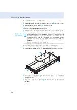
왘
Secure the rack mount “ears”
to the sides of the receiver using the
previously removed recessed head screws (see right-hand diagram).
Fitting the
device feet
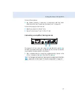
왘
Clean the base of the receiver where you want to fix the device feet.
왘
Fit the device feet to the four corners of the receiver as shown.
왘
Place the receiver on a flat, horizontal surface.
Connecting the
rod antennas
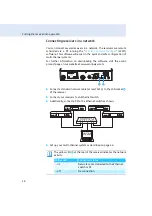
The supplied rod antennas
can be mounted quickly and easily and are
suitable for all applications where – good reception conditions provided –
a wireless transmission system is to be used without a large amount of
installation work.
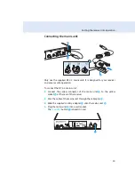
왘
Connect the two rod antennas
to the BNC sockets
and
rear of the receiver.
왘
Align the rod antennas upwards in a V-shape.
Do not fit the device feet when mounting the receiver into a
19” rack.
XXX - XXX
MHz
FREQ. RANGE-
X:
SER. NO.:
XXXXXXXXXX
TRUE DIVERSITY
RECEIVER
EM 50
0
IDENT
. NO.:
XXXXXX
IC: 2099A-
XXXXXXX
DESIGNED IN GERMANY
, ASSEMBLED IN USA
0682
XXX - XXX
MHz
FREQ. RANGE-
X:
SER. NO.:
XXXXXXXXXX
TRUE DIVERSITY
RECEIVER
EM 50
0
IDENT
. NO.:
XXXXXX
IC: 2099A-
XXXXXXX
DESIGNED IN GERMANY
, ASSEMBLED IN USA
0682
Summary of Contents for EM 500
Page 1: ......


