background image

6/8

ELECTRICAL CONNECTIONS

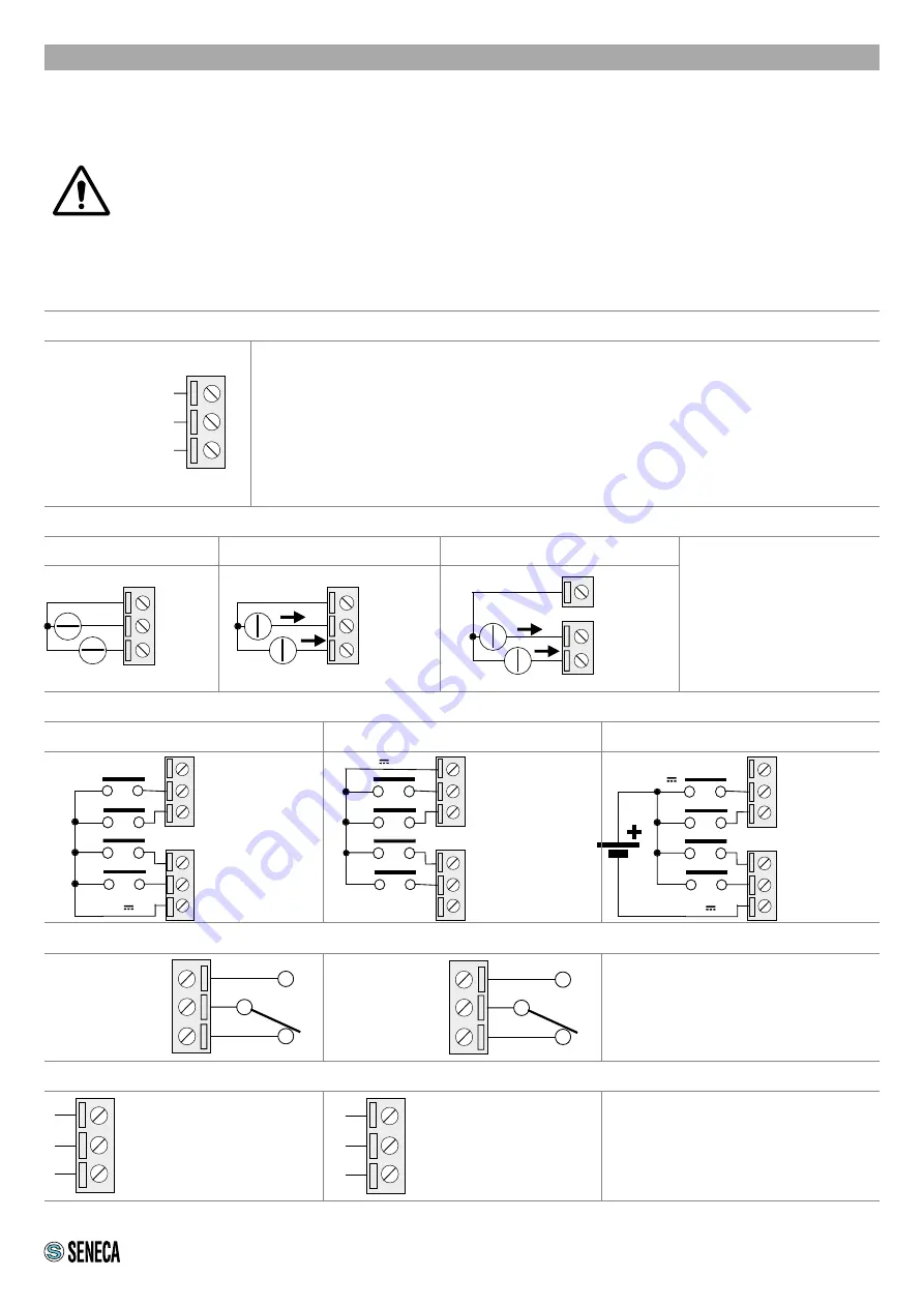
10 GND
11 A(+)
12 B (-)

10 GND
11 RX
12 TX

N.A.2=22

CO.2=23

N.C.2=24

N.A.1=19

CO.1=20

N.C.1=21

13 DI1

14 DI2

15 +12V

16 GND

17 DI3

18 DI4

0V

Max 24V

12V 20mA

13 DI1

14 DI2

15 +12V

16 GND

17 DI3

18 DI4

13 DI1

14 DI2

15 +12V

16 GND

17 DI3

18 DI4

0V

2

1

3

5A I1
6A I2

1 12V

4GND
5AI1
6AI2

+

+

+

+

Attention: the upper power supply limits must not be exceeded, as this might cause serious damage to 

the module.

To meet the electromagnetic immunity requirements:

- use shielded signal cables;

- connect the shield to a preferential instrumentation earth system;

- separate shielded cables from other cables used for power installations (transformers, inverters, motors, 

induction ovens, etc...).

POWER SUPPLY

The power supply is connected to terminals 2 and 3. 

The supply voltage must be between: 

11 and 40Vdc (indifferent polarity), or between 19 and 28 Vac. 

The power supply source must be protected from any failures in the 

module by means of a suitably sized fuse.

Power supply
Power supply

Auxiliary voltage

+12 Vdc a 3 mA

ANALOGUE INPUTS 

DIGITAL INPUTS (ONLY ZE-4DI-2AI-2DO and Z-4DI-2AI-2DO)

DIGITAL OUTPUTS (ONLY ZE-4DI-2AI-2DO and Z4DI-2AI-2DO)

COM2 SERIAL PORT

4GND

5AI1
6AI2

Voltage

Active sensor current (4 wires)

Passive sensor current (2 wires)

The module has two 

analogue inputs that can be 

configured via software as 

voltage or current.

For the configuration 

software, see the user 

manual

RS485 


SERIAL 


PORT

(SW2=OFF)

RS232 

SERIAL 

PORT

(SW2=ON)

The has two digital outputs with free 

contacts.

The two figures show the internal relay 

contacts available.

The module has a COM2 port 

configurable via the SW2 switch  

on terminals 10 -11-12

Summary of Contents for ZE-4DI-2AI-2DO

Page 1: ...visit www seneca it products ze 4di 2ai 2do www seneca it products z 4di 2ai 2do www seneca it products ze 2ai EN MI00543 0 EN 1 8 ZE 4DI 2AI 2DO Z 4DI 2AI 2DO ZE 2AI This document is the property of SENECA srl Copies and reproduction are prohibited unless authorised The con tent of this document corresponds to the described products and technologies Stated data may be modified or supplemented for...

Page 2: ...F 4V ON 8V max 24 Vdc Current input 20mA Max frequency 5 KHz Absorbed current 3mA 12Vdc 10mA 24Vdc COUNTERS only ZE 4DI 2AI 2DO Z 4DI 2AI 2DO 4 x 32 bit resettable counters on non volatile memory DIGITAL OUTPUTS only ZE 4DI 2AI 2DO Z 4DI 2AI 2DO Number of channels 2 SPDT free contact relay Max voltage 250 Vac Max current 2A ANALOGUE INPUTS Number of channels 2 Configurable mAdc or Vdc Voltage inpu...

Page 3: ...Union and other countries with recycling The symbol on the product or its packaging shows the product must be surrendered to a collection centre authorized to recycle electrical and electronic waste The module must be repaired and damaged parts replaced by the Manufacturer The product is sensitive to electrostatic discharges Take appropriate measures during any operation SETTING THE DIP SWITCHES T...

Page 4: ...g ducting or other objects that obstruct the ventilation slots Avoid mounting modules over heat generating equipment Installation in the bottom part of the electrical panel is recommended Insertion in the DIN rail As shown in figure 1 Insert the IDC10 rear connector of the module on a free slot of the DIN rail the insertion is univocal since the connectors are polarized 2 To secure the module to t...

Page 5: ...oducts supported by the Easy Setup APP in the store 5 8 Power supply and Modbus interface are available using the Seneca DIN rail bus via the IDC10 rear connector or the Z PC DINAL 17 5 accessory RS485GND RS485A RS485B Power Supply AC Power Supply AC IDC 10 1 Back connector IDC 10 The illustration shows the meanings of the various IDC10 connector pins if signals are to be sent via them directly Po...

Page 6: ...upply is connected to terminals 2 and 3 The supply voltage must be between 11 and 40Vdc indifferent polarity or between 19 and 28 Vac The power supply source must be protected from any failures in the module by means of a suitably sized fuse Power supply Power supply Auxiliary voltage 12 Vdc a 3 mA ANALOGUE INPUTS DIGITAL INPUTS ONLY ZE 4DI 2AI 2DO and Z 4DI 2AI 2DO DIGITAL OUTPUTS ONLY ZE 4DI 2AI...

Page 7: ...Green ON Module powered and IP address acquired IP PWR Green Flashing Module powered and IP address not yet acquired or ETH port not connected Tx Rx Red Flashing Transmission and reception of data on at least one Modbus port port 1 RTU port 2 RTU ETH TRF Green Flashing Packet transmission on Ethernet port ETH LNK Yellow ON Ethernet port connected DI1 DI2 DI3 DI4 Red On Off Status of digital input ...

Page 8: ...N At least one of the two analogue inputs is out of scale underscale overscale ETH TRF Green Flashing Packet transmission on Ethernet port ETH LNK Yellow ON Ethernet port connected Tx1 Red Flashing Modbus packet transmission from device to port 1 RTU Rx1 Red Flashing Modbus packet transmission to port 1 RTU Tx2 Red Flashing Modbus packet transmission from device to port 2 RTU Rx2 Red Flashing Modb...

Reviews: