MI00205-7-EN
INSTALLATION MANUAL
3/4
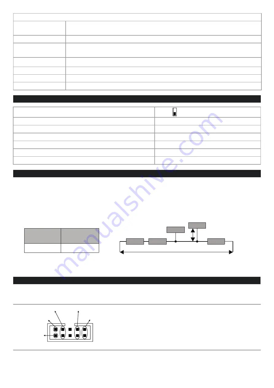
INPUTS
Type of supported
inputs:
Reed, Contatto, proximity PNP, NPN (with external resistance)
Number of channels:
5 (4+ 1) self-powered at 16Vdc
Totalizer maximum
frequency
100 Hz for channels from 1 to 5
10 kHz only for input 5 (after setting)
U
L
(status OFF)
0 ÷ 10 Vdc, I < 2mA
U
H
(status ON)
12 ÷ 30 Vdc; I > 3mA
Absorbed current
3mA (for each active input)
Protection
By means of transient TVS suppressors of 600 W/ms.
CONFIGURATION OF FACTORY SETTINGS
All DIP-switches in
OFF
Communication parameters of ModBUS protocol:
38400 8, N, 1 Address 1
Input status inversion:
DISABLED
Digital filter
3ms
Totalizers
Counting to increment
Channel 5 at 10 KHz
Disabled
ModBUS latency time
5ms
1200 m
2 m
2
1
4
5
Ld
Diagram 1
Bus length
Derivation
length
Module
Module
Module
Module
Module 3
Bus length
Ld= derivation length
ModBUS CONNECTION RULES
1) Install the modules in the DIN rail (120 max)
2) Connect the remote modules using cables of an appropriate length. The following table shows cable length data:
- Bus length: maximum length of the Modbus network according to the Baud Rate. This is the length of the cables
that connect the two farthest modules (see Diagram 1).
- Derivation length: maximum length of a derivation 2 m (see Diagram 1).
For maximum performance, it is recommended to use special shielded cables, such as BELDEN 9841.
IDC10 CONNECTOR
Power supply and Modbus interface are available using the Seneca DIN rail bus, via the IDC10 rear connector, or the
Z-PC-DINAL2-17.5 accessory.
RS485 GND
RS485 A
RS485 B
Power Supply AC / +
Power Supply AC / -
IDC 10
1
Rear Connector (IDC 10)
The meaning of the various pins on the IDC10 connector
is shown in the figure if you wish to supply signals directly
via it.


