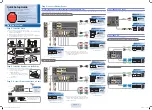
mA input
+
The loop is powered
by the module (17 V Loop)
CURRENT INPUT
mA input (2 wires)
VOLTAGE INPUT
3.0 W
10 ÷ 40 V
DC
19 ÷ 28 V
AC
1
2A
POWER SUPPLY: Verify the code on the applied label
.
9
9
10
10
8
7
+
8
7
9
10
8
7
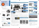
6. ELECTRICAL CONNECTIONS
4.4 Password for access to the menu
Code
S312A-4-L-4R
3.0 W
85 ÷ 265 V
AC
1
2B
Code
S312A-4-H-4R
+
2 wires
9
10
8
7
PT100 INPUT
3 wires
4 wires
9
10
8
7
9
10
8
7
THERMOCOUPLE INPUT
+
Resistance R=330
(not provided),
P=1 k 100 k
POTENTIOMETER INPUT
R=330
P
10
9
8
7
9
10
8
7
The loop is powered
by the sensor
It is possible to enable the protection of the Programming Menu by password.
The Quick Alarm Menu is instead password free.
ENGLISH - 4/21
MI00250 -E
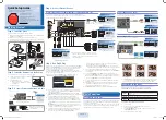
3
Rs485
Led
2
2 2
2
2
2
3
1
Alarm 3/1
Led
Alarm 4/2
1
9
8
7
1 2A 2B
6
5
4
3
10
DOWN
OK/MENÙ
UP
Relay
1
4
2
1
1
1
0
8
9
7 1
1
1
1
1
1
6
3
5
2
4
1
F
: B
L
RONTAL PANEL
UTTONS AND EDS
REAR SIDE: TERMINALS
Pow. Supply
Output
Input
5. BUTTONS AND TERMINALS POSITION
Relay
2
Relay
3
Relay
4
3
Summary of Contents for S312A-4-H-4R
Page 17: ...MI002502 E 11 11 1 11 2 11 3...
Page 18: ...MI002502 E 11 7 11 4 11 5 11 6 DEFAULT SETTING SYSTEM...
Page 19: ...MI002502 E...
Page 20: ...MI002502 E...


