


Kingfisher Plus+ Hardware Manual
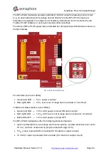
Note that the crowbar protection circuit will latch when its voltage is either below -0.5 V or
above +18.5 V (approximately). It will clamp the input power rail voltage to a very low value:
± (0.5 – 2.5) V depending on the clamp current supplied by a power source. If the power
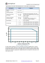
source can provide current exceeding a polyfuse trip current (3-24 A depending on the
ambient temperature), it may trip also, limiting the clamp current to several milliamperes.
To recover protective circuit after tripping, the input voltage should be removed completely.
A 5-10 s pause before re-applying input power may be required to allow for the polyfuse to
cool down if it has tripped.
WARNING. Install BP-x-PLUS as close to the power source as practically possible. To avoid
tripping of the overvoltage / reverse polarity protection circuit, that may occur due to voltage
overshoots caused by the parasitic inductances of the long wires, the power wires length
should not exceed 3 m. Install a 330 - 1000 µF (rated 25 V minimum) capacitor as close as
practical to the input power terminals of the BP-x-PLUS backplane if high levels of
electromagnetic interferences may be present at the installation site.
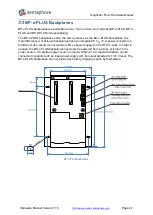
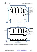
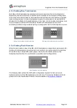
There are no adjustable or serviceable parts on the BP-x-PLUS backplanes. Since these
backplanes are not configurable, their rack number is always fixed to #1 and their slot
numbering always starts from 1. Therefore, only one BP-x-PLUS backplane can be used in
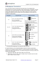
the RTU. However, Power and/or Data Connectors to extend the RTU using BA-x-PLUS
backplanes are available.
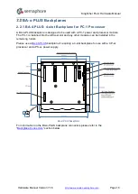
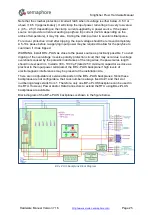
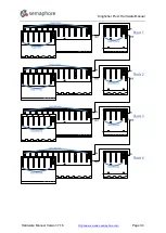
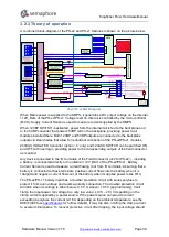
Block-diagram of the BP-x-PLUS backplanes is shown in the figure below.
BP-x-PLUS backplane Block Diagram
Hardware Manual Version 7.16
http://www.servelec-semaphore.com/
Page 25


