Selco Sistor 82 Instruction Manual Download Page 9

18

12.1 Plasma cutting process

The cutting action is obtained when the plasma arc, made very

hot and highly concentrated by the design of the torch, transfers

onto the conductive piece to be cut, closing the electrical circuit

with the generator. The material is first melted at a high tempe-

rature of the arc, and then removed by the high exit velocity of

the ionized gas from the nozzle.

The arc can have two different states: that of the transferred arc,

when the current passes through the piece to be cut, that of the

pilot arc or non-transferred arc, when this is sustained between

the electrode and the nozzle.

13.0 CUTTING SPECIFICATIONS

In plasma cutting, the thickness of the material to be cut, the

speed of cutting and the current supplied by the generator have

values which are related to each other; these depend on the type

and quality of the material, type of torch as well as the type and

condition of the electrode and nozzle, distance between nozzle

and piece, pressure and impurity of the compressed air, cut qua-

lity required, temperature of the piece to be cut, etc.

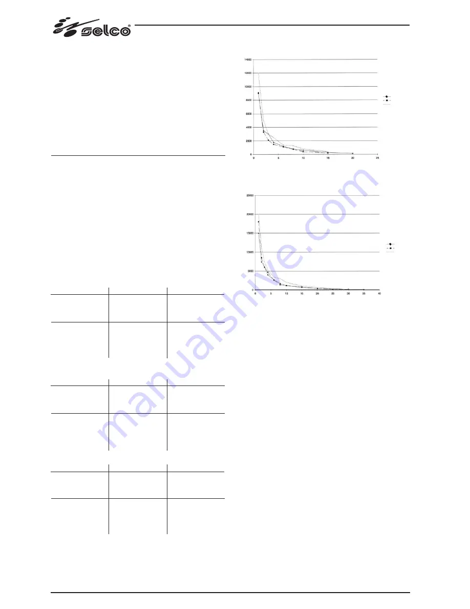
In the diagrams as in Fig.8, 9 we can see that the thickness to be

cut is inversely proportional to the cutting speed, and that both

these values can be increased with an increase in current.

The cutting tests have been performed in standard operating

conditions using a Trafimet torch at 90A.

MILD STEEL

STAINLESS STEEL

ALUMINIUM

* High quality cut

Fig. 8

Fig. 9

Thickness (mm)

3

6

10

15

3

6

10

20

30

Current (A)

50

50

50

50

80

80

80

80

80

Speed (mm/min)

3000

1200

600

300

6000

2700

1200

450

200

Thickness (mm)

3

6

10

15

3

6

10

20

25

Current (A)

50

50

50

50

80

80

80

80

80

Speed (mm/min)

2100

1000

400

200

6000

2600

1200

400

200

Thickness (mm)

3

6

10

15

3

6

10

20

25

Current (A)

50

50

50

50

80

80

80

80

80

Speed (mm/min)

3000

1400

800

400

7300

3400

2000

700

400

CUTTING SPEED WITH 50A

SPEED (mm/min)

SPEED (mm/min)

CUTTING SPEED WITH 80A

THICKNESS (mm)

MILD STEEL

STAINLESS STEEL

ALUMINIUM

MILD STEEL

STAINLESS STEEL

ALUMINIUM

THICKNESS (mm)

Summary of Contents for Sistor 82

Page 1: ...r 82 ISTRUZIONI PER L USO INSTRUCTION MANUAL BETRIEBSANWEISUNG MANUEL D INSTRUCTIONS INSTRUCCIONES DE USO MANUAL DE INSTRU ES GEBRUIKSAANWIJZING BRUKSANVISNING BRUGERVEJLEDNING BRUKSANVISNING K YTT OH...

Page 2: ...12 1 1 Operator and other persons protection 12 1 2 Fire explosion prevention 12 1 3 Protection against fumes and gases 12 1 4 Positioning the power source 12 1 5 lnstalling the apparatus 12 1 6 Preca...

Page 3: ...es have been opened emptied and carefully cleaned the welding cutting operation must in any case be perfor med with great care Do not weld cut in places where explosive powders gases or vapours are pr...

Page 4: ...s must be kept as short as possible positio ned near one another and laid at or approximately at ground level EQUIPOTENTIAL CONNECTION The earth connection of all the metal componente in the welding c...

Page 5: ...c power to the welder It has two positions O off and I on With the I1 switch in the I on position the welder is operational The welder is connected to the mains supply even if the I1 switch is in the...

Page 6: ...ment or the single unit fall nor put it down with force 6 0 INSTALLATION Choose an adequate installation area by following the criteria provided in Section 1 0 SAFETY and 2 0 ELECTROMAGNETIC COMPATIBI...

Page 7: ...be cut ensuring that it makes a good electric connection Fig 6 4 Check that all the components of the torch are present and correctly fitted and connect the torch fitting to the connector on the gener...

Page 8: ...thus beco ming electrically conductive Although the plasma exists in every electric arc by the term plasma arc we refer specifically to a torch for welding or cut ting that uses an electric arc made t...

Page 9: ...nd condition of the electrode and nozzle distance between nozzle and piece pressure and impurity of the compressed air cut qua lity required temperature of the piece to be cut etc In the diagrams as i...

Page 10: ...99 Targa dati Nominal data Leistungschilder Plaque des donn es Placa de caracter sticas Placa de dados Technische gegevens M rkpl t Dataskilt Identifikasjonsplate Arvokilpi...

Page 11: ...ttribu de soudure decoupage 15B 16B 17B Valeurs de la tension conventionnelle de charge 18 Symbole pour l alimentation 19 Tension attribu e d alimentation 20 Courant maximum attribu d alimentation 21...

Page 12: ...101 Schema Diagram Schaltplan Sch ma Esquema Diagrama Schema kopplingsschema Oversigt Skjema Kytkent kaavio...

Page 13: ...arts list Ersatzteilverzeichnis Liste de pi ces d tach es Lista de repuestos Lista de pe as de reposi o Reserveonderdelenlijst Reservdelslista Liste med reservedele Liste over reservede ler Varaosalue...

Page 14: ...Leistungstransformator 05 01 1521 17 Gummirad 04 03 001 18 H F Karte 15 14 192 19 Regler Filter 24 02 010 20 Solenoidventil 09 05 001 21 Logikkarte 15 14 087 22 Zweipoliger Schalter 09 01 001 23 Griff...

Page 15: ...erators Alarm f r zu niedrigen Luftdruck bertemperaturalarm Gaspr fung Lichtbogen ein FRAN AIS Arr t g n rateur Allumage g n rateur Alarme g n rale Alimentation du g n rateur Alarme pression de l air...

Page 16: ...s r l Via Palladio 19 35010 ONARA DI TOMBOLO PADOVA ITALY Tel 39 049 9413111 Fax 39 049 9413311 http www selco it E mail selco selco it SELCO 2 Via Macello 61 35013 CITTADELLA PADOVA ITALY Codice 91 0...

Reviews: